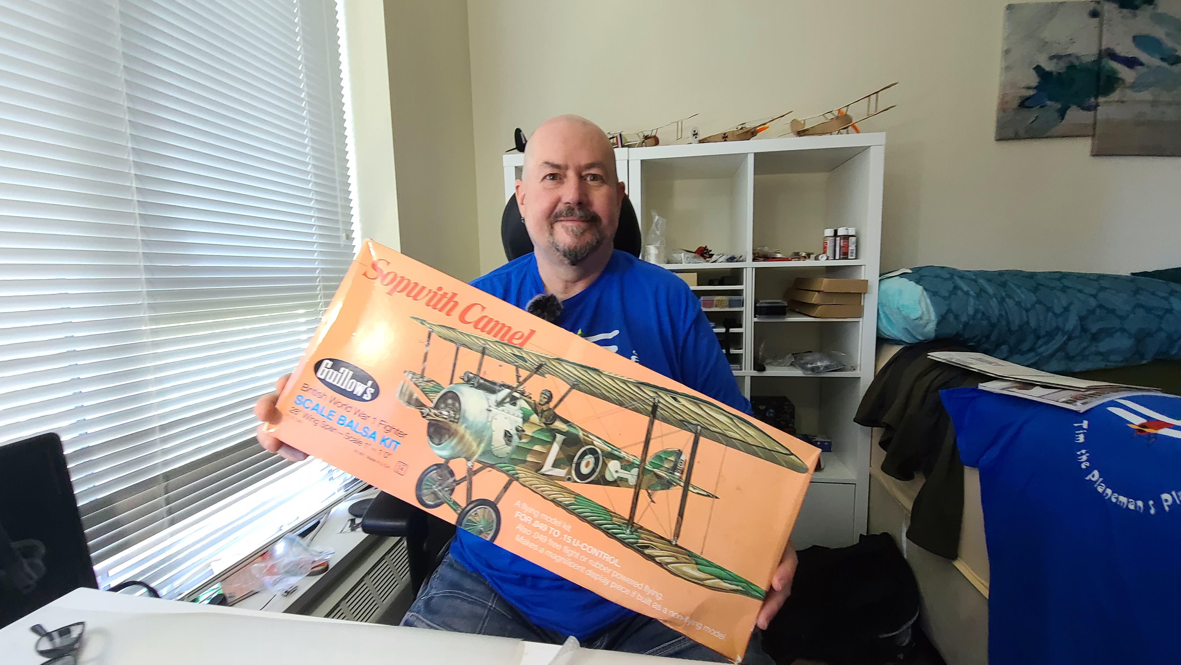
Figuring out the aileron servos for the Guillows Sopwith Camel 801 build (see the post about the build here) has been a very interesting journey. So I’ve created this separate post to write up just the ailerons. Hope it helps.
There is also a YouTube video with a demo of the working ailerons (still under construction) on my Tim the Plane Man channel.

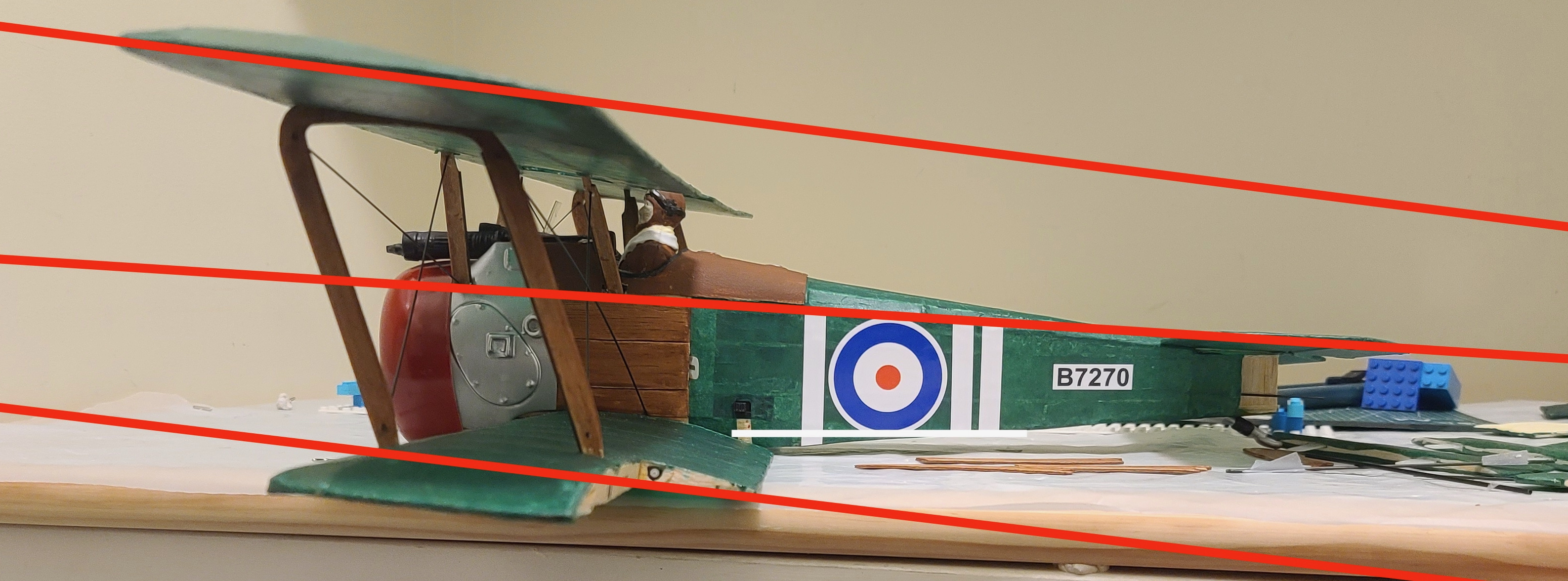
The out of the box plan has moveable ailerons, but only for static display. They are not intended to be functional. So I want to have ailerons and I want them on top and bottom wing.
Both Cliff Harvey with his Guillows Spitfire, and Tim McKay who had a similar experience with the Guillows Zero, pretty much proved that the control of ailerons is going to be essential to making this plane behave nicely when it flies. So I have to solve two problems 1. Getting ‘control’ out to the end of the wings. 2. Getting the control up from the bottom wing to the top wing.
First I’m going to mount servos out on the wing. I’m actually thinking that because this is a biplane which will have 4 ailerons, the torque required for each of them is much smaller as its divided by 4.
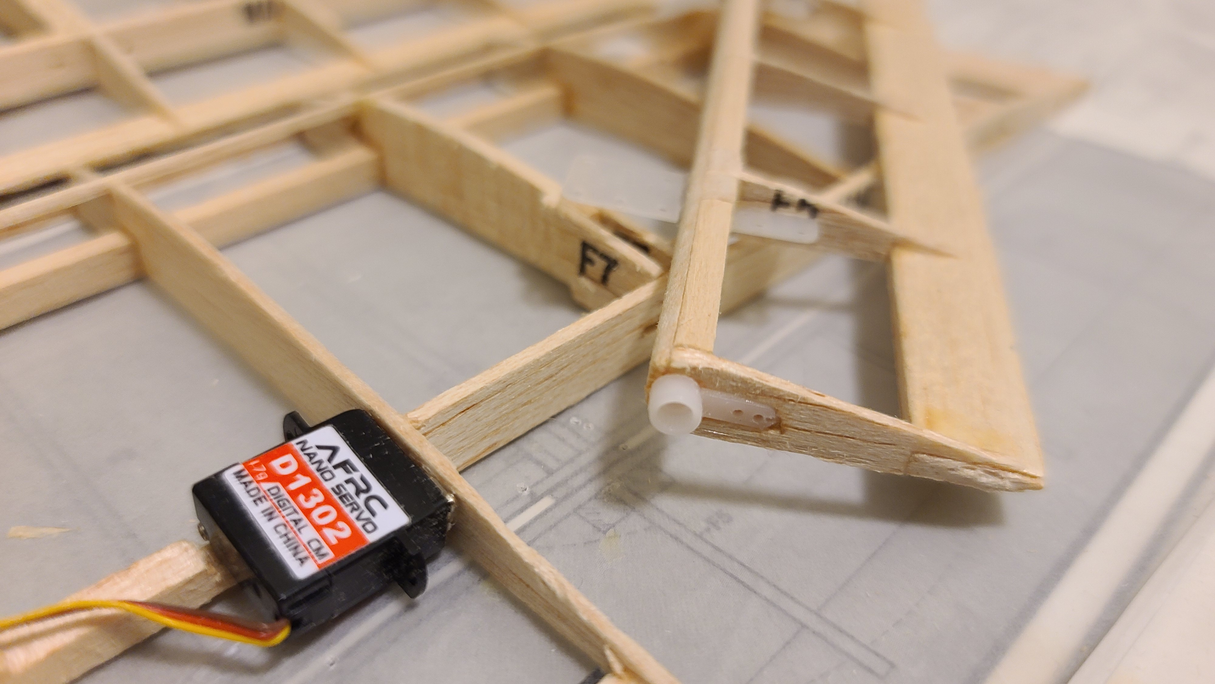
So I’ve been doing more thinking and shopping and found some absolutely amazing tiny 1.7g AFRC D1302 digital servos that have torque of 0.15 kg/cm (0.014 Nm) which is exactly what is required for ailerons of this size according to at least 2 different surface area/torque calculators I have found online.
So I am going to do an experiment – using direct drive of the ailerons using these wonderful little digital servos.
Calculations
Trying to figure out exactly how much torque is actually required for a servo isn’t easy. What seems to have happened is that many years ago someone figured out that a 9g servo was “good enough” – and was pretty light compared to the weight of other components so everyone just kept using 9g servos.
But like most other areas of technology in this ever-changing world we live in, the technology of servos is improving in leaps and bounds. This is being driven by other uses of servos such as robotics. To me this means it makes sense to ask two simple questions:-
- How much torque is required for a particular purpose?
- What is the smallest servo I can use to give me that torque?
For the Sopwith Camel, I have a target weight in mind of 180g. If I don’t meet that, the absolute worst case I want is < 250g. This means weight is important, and if (for example) I can shave off 20-30g or more by switching out 4x or even 6x 9g servos for some much smaller digital servos, I’m all for it.
I did a lot of research (i.e. Googling) about this, with not a lot of results. I have basically found 2 web sites that seem to have usable and understandable formulas for calculating torque.
There is a calculator at Radio Control Info. This is ok but doesn’t explain its formula, so I am suspicious of it. I use it to validate my own calculations. This one is also very strange as it asks for all the input parameters in metric and then gives the results in “oz-in”. This is confusing and annoying.
Minnesota Big Birds has a page with a fully documented torque calculation formula by Chuck Gadd. I love this. The rational and mathematics are out there in the open and explained and I can put this into spreadsheet and do my own calculations and even tweak it. This is their formula:
Torque (oz.-in) = 8.5E-6 * (C2 V2 L sin(S1) tan(S1) / tan(S2))
Where:
§ C = Control surface chord in cm
§ L = Control surface length in cm
§ V = Speed in MPH
§ S1 = Max control surface deflection in degrees
§ S2 = Max servo deflection in degrees
Of course this is also frustrating because it uses “Miles per hour” (remember miles? – something from the old British Empire I think), and gives the results in oz-in instead of Nm or even kg-cm. But having the formula it’s pretty easy to update it to use modern metric units. Miles/hour to km/hour is easy – Just need to multiply by 0.621371^2, so that just changes the constant at the front. The result can be converted to km-cm by multiplying by 0.07200778893234 or 0.00706155 to get Nm which is actually the proper metric unit for torque. Most servos are sized in kg-cm (or oz-in, I’ll ignore that), so the new formula is
Torque (Nm) = 0.0000000231750630904477 * (C2 V2 L sin(S1) tan(S1) / tan(S2))
Torque (Kg-cm) = 0.000000236319937054984 * (C2 V2 L sin(S1) tan(S1) / tan(S2))
Lastly there is a pdf thoroughly documenting servo torque requirements by Andy Meysner of the Southern Ontario Glider Group, which is the one I like the best so far. It refers to the other two, but this explains how the formula works in details and it calculates using metric inputs, and gives the results in Nm. as it says:
Servo torque is usually specified in oz-in or kg-cm. To obtain the torque in oz-in or kg- cm, multiply the result in N-m by 141.6 or 10.2 respectively
https://soggi.ca/wordpress/wp-content/uploads/2020/09/ServoTorqueCalcArticle_App.pdf
The whole formula assuming a servo arm, control rod and control horn on the control surface is:
Ts = V2 x L x C2 x sin(αh) x tan(αh)/ (4 tan(αs))
(assuming Cd – drag coefficient = 1.0 and p = 1.2. Read the article for details)
V = Airspeed in m/s (multiply km/hour by 0.277778)
L = Length of the control surface in meters (3.5 cm = 0.035 meters)
αh is the rotation angle of the control surface from neutral in degrees
αs is the rotation angle of the servo arm in degrees measured from the servo arm position at 900 to the pushrod – I’m assuming αh= αs (I hope this is valid but I think it should be)
But here is where it gets interesting, Andy’s article also explains in detail how the calculation is done and as part of the calculation, it shows the calculation for the torque on the control surface itself as an intermediate step. This is fascinating because this would be the torque required for a direct drive servo like the one I plan to use on the ailerons on the Sopwith Camel. The formula for this would be:
T = ((Cd ρ V2 C L sin(αh))/2) C / 2
(again Cd = 0, p = 1.2)
Note that C appears multiple times, so this can be simplified to
T = ρ V2 C2 L sin(αh)/4
For the ailerons of the Sopwith Camel, which has:
- Chord = C = 3.5 cm or 0.035m
- Length = L = 14 cm or 0.014m
- Speed = V = 50 km/hour (I’m making an assumption here)
- Control surface deflection = servo deflection = 20 degrees
So the results for the Sopwith Camel ailerons are:
Torque kg-cm: 0.14 – which is less than the 0.15 spec for the 1.7g digital servos I’m using
Interestingly I did the calculations for the all the control surfaces and this is the result:
| Surface | Chord | Length | Deflection | Speed Km-hour | Torque [Big Birds] | Torque [Meysner] |
| Ailerons | 3.5 cm | 14 cm | 25 degrees | 50 km/hr | .043 kg/cm .004 Nm | .044 kg/cm .004 Nm |
| Elevator | 3 cm | 18 cm | 20 degrees | 50 km/hr | .088 kg/cm .008 Nm | 0.033 kg/cm .003 Nm |
| Rudder | 4.5 cm | 8 cm | 20 degrees | 50 km/hr | .087 kg/cm 0.008 Nm | .035 kg/cm .003 Nm |
[I’m not sure why there is such a discrepancy between the Big Bird and Meysner numbers for elevator and rudder while the aileron numbers are so similar. I think I might have an error in my spreadsheet somewhere – more digging required].
This was a very long winded way to show that the 0.15 kg/cm digital servos at 1.7g that I plan on using, have approximately 3X the required torque for the Sopwith Camel ailerons!
It also means that I should probably be able to use the same 1.7g servos for elevator and rudder, although I had been planning to use some 3.7g servos I have for those controls. I’m not sure what I will do about that yet (2021-07-30).
Installation
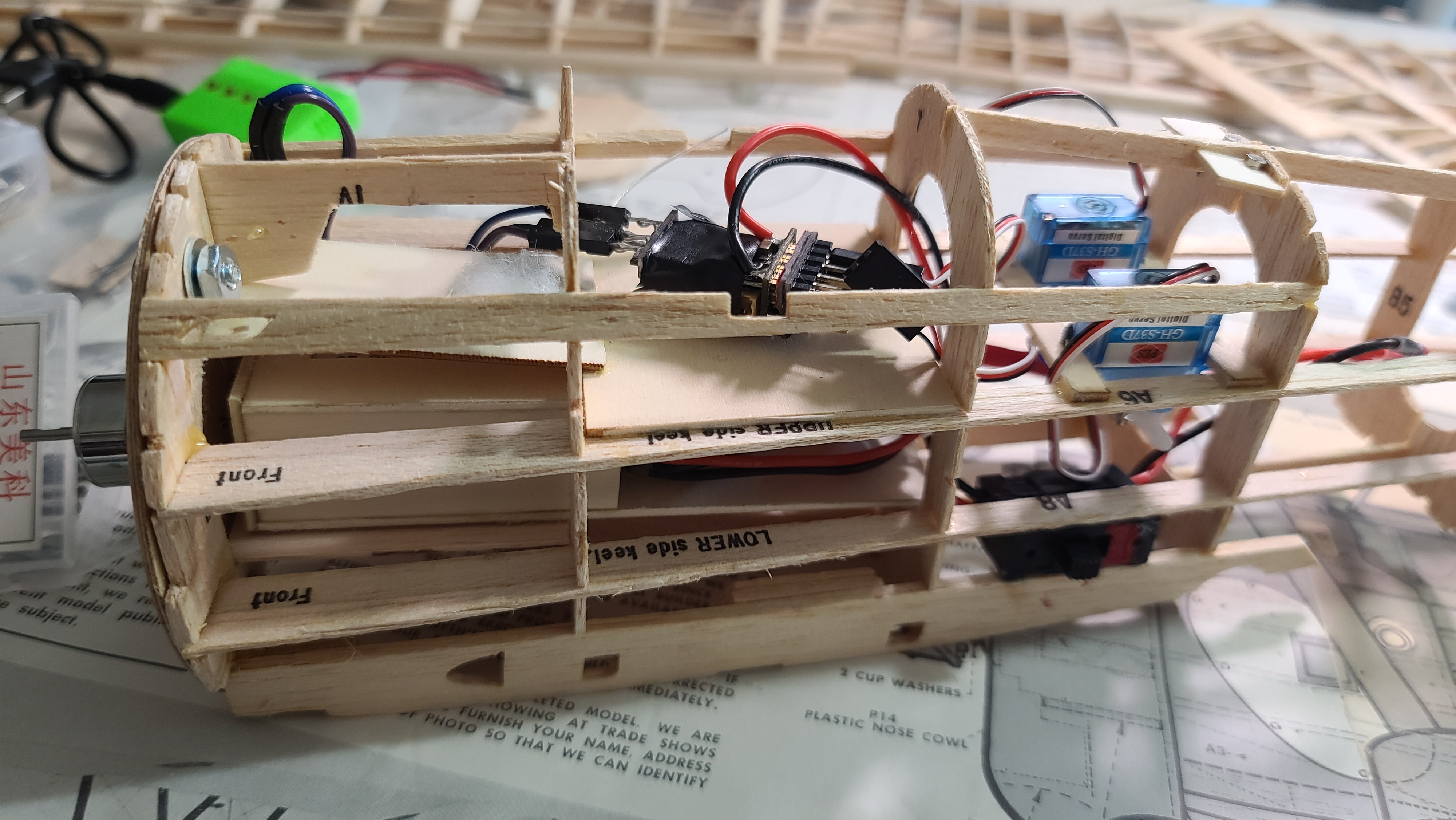
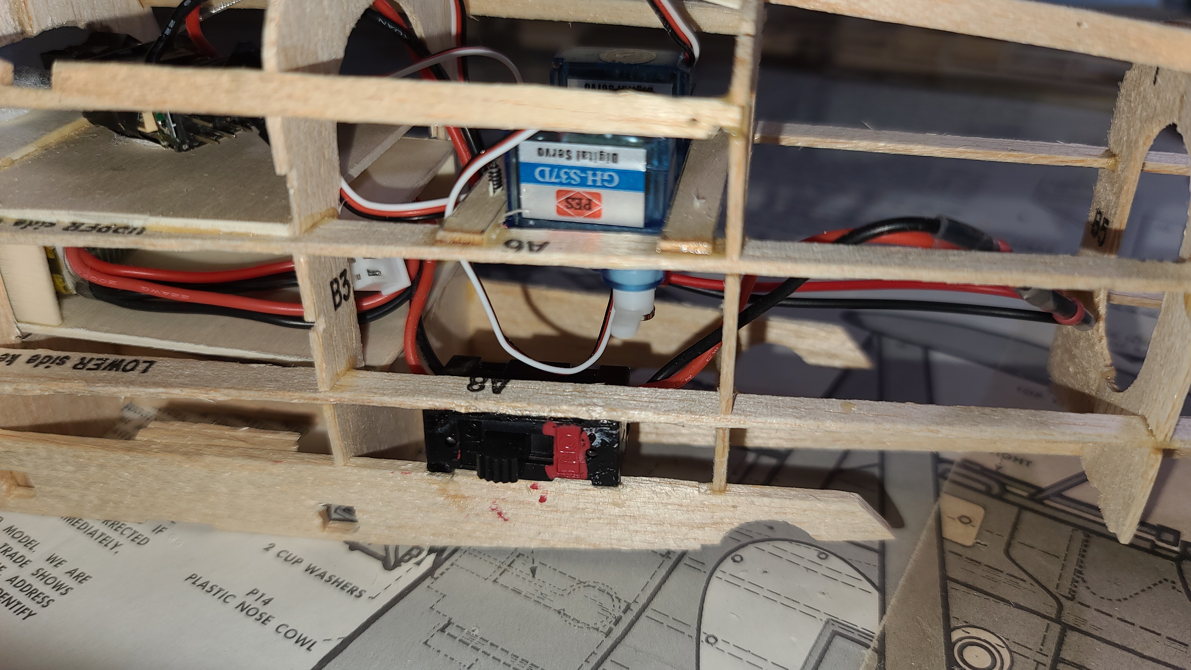
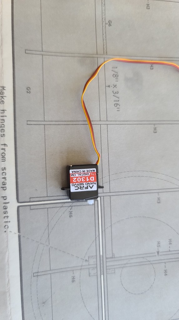
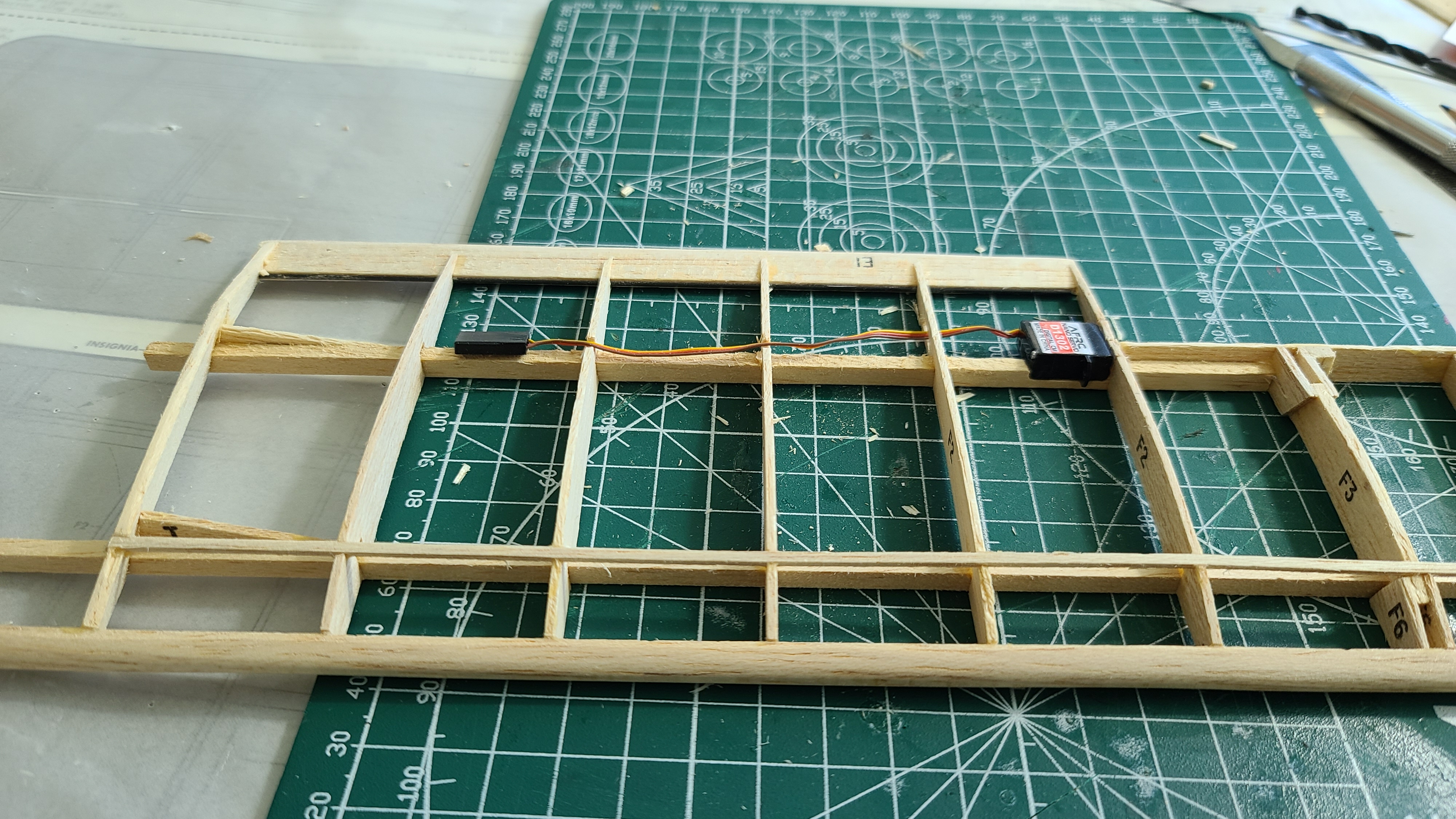
I’ve started installing the first of possibly 4 aileron servos directly inside the wing next to the ailerons. They will be direct drive which cuts out a lot of weight and inefficiency. These will be 1.7g digital servos. It seems to make sense. See my YouTube video that shows how it works.
Wires
Running the wires from the aileron to the fuselage is an interesting challenge. I see most people end up putting holes in the middle of the ribs. It struck me while I was doing this that I was weakening the weakest part of the rib by doing this. Why not, I thought, run the wires along the spar, which is the strongest part of the wing, and would make for the easiest place to run the wires while also making them less visible if I use tissue paper for the covering (which I haven’t decided on yet). This is how it looks.
The next thing is to figure out how to connect the wires to the receiver. I had been planning to have 2 channels and a Y cable on each channel, a bit like running a 2 channel mix driver for ailerons on a single wing plane, but using the Y to split the signal so the upper and lower wing each get the same signal.
Rob Mawer on the Guillow’s Facebook group suggested another option – use 4 channels with separate wires to each servo. This wouldn’t add much more weight, but would make it easier to centre and trim each servo if they are on separate channels. It makes the model setup in the transmitter a little tricky, but with OpenTX, it should be doable. Right now I’m thinking of this as a backup plan, but that might change when I build the upper wings. Stay tuned!
Upper wings
Well I thought the upper wings were going to be easy. Just use a Y connector to drive the upper wing from the same receiver channel as the lower wing. I would do a 2 channel aileron mix in the Jumper T-Lite, OpenTX makes it so easy. But after I posted on YouTube and Facebook, this was the first thing people called into question.
Rob Mawer on Facebook groups pointed out that centering and trimming the two ailerons might be tricky if the two ailerons were not exactly aligned. He suggested using a 4 channel design so each servo could be centered and trimmed separately. The OpenTX setup would be very custom, but doable.
This also makes me think that using the Y to split the signal on the same side might not be as smart as running the upper wings with one Y on one channel and then the lower wings on a second Y on a second channel. This would mean the ailerons are centered and trimmed as per a normal single channel arrangement, but it would have to be done twice, once for the lower wings and once for the upper wings. I kind of like this idea.
Cliff Harvey RC Planes on YouTube suggested that ailerons on the upper wings might not even be necessary, the ones on the lower wings might be enough. I’m definitely drawn to this idea, it makes things much simpler.
Irwin Weisbrot on YouTube suggested that I could mechanically link the lower aileron to the upper which would mean I would not need a servo in the upper wing. This is attractive since it is very similar to how the real plane was built, and if I got it right it would look very “scale”, but it would double the thrust that the servo would be working against and therefore the amount of torque required. My calculations right now have a lot of ‘fudge factor’ and the two different methods give so different results, that I’m not convinced this would be safe. I might keep this in my back pocket.