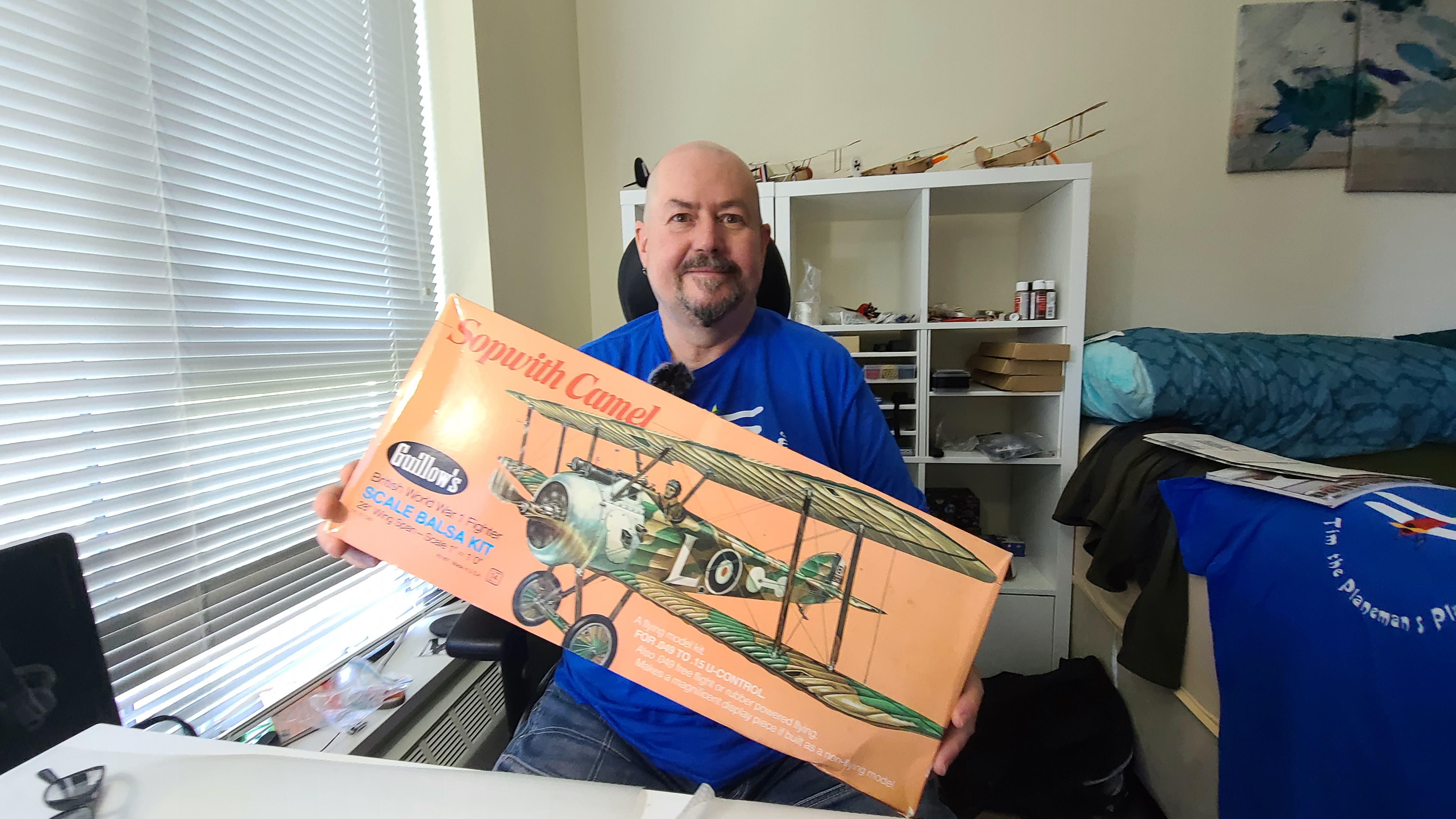
I just opened [20 June 2021] my “new” Sopwith Camel kit from Guillows. I say “new”, but I bought this off eBay because at the time I ordered it, the Guillows website was Out of Stock. So the “new” kit I bought from eBay is actually pretty old. It’s well preserved, but the paper is yellowing and the box doesn’t have the “Laser Cut” sticker that the new models have. So this model is die-cut, the old way, pre the modern days of laser cut balsa.
This is quite fun because some of the things included in the box are things you will never see any more. Like a paper order form for ordering replacement parts by sending the form and a cheque (remember cheques?) to Paul K. Guillow Inc. Box 229, Wakefield, MA, 01880.
The copyright notices on the plans and the enclosed catalog say 1973 and 1974. The stamped model number on the kit pieces say “801-1”. I can’t be sure but I think this kit is about 50 years old.
Luckily all of the wooden pieces are well preserved, except for the plywood containing some of the slats and frame pieces which is a bit warped. I’m soaking this in water and trying to dry it flat. This worked out fine.
Review of Instructions
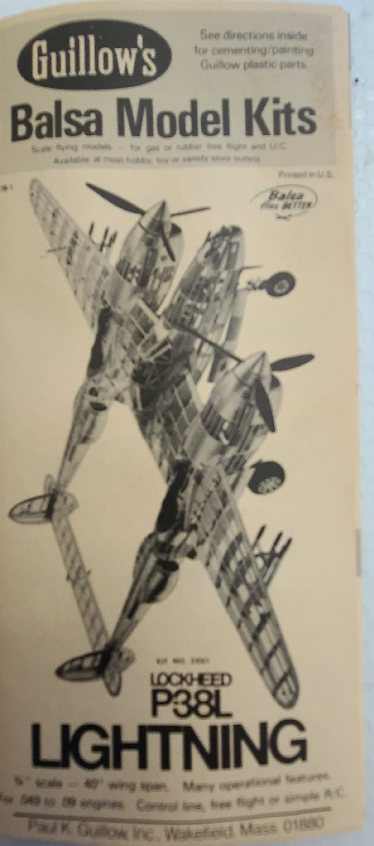
Having opened the box, the first thing I did was read the instructions. There were some very interesting things in these instructions, not all relevant to building the plane, but I thought I’d just note them as I go.
Copyright 1973
The copyright on these plans is 1973, and the copyright on the little “Catalog” included in the box, is 1974. Now this doesn’t prove the kit is that old, but it is certainly interesting. I haven’t found anything dated more recently than 1974.
It’s also very interesting that included in the kit was an “order form” for ordering replacement parts.
U-Control
The kit is made for rubber powered free flight or “U-Control”. I didn’t know what that was, but I did figure it out. It is what used to do when I was a teenager building and flying “control line” planes – flying around in a circle controlled by wires and a little handle. You tilt your hand to make the plane go up and down. The kit even includes the handle (but no wires) and I didn’t know what it was at first. It’s for control line flying!
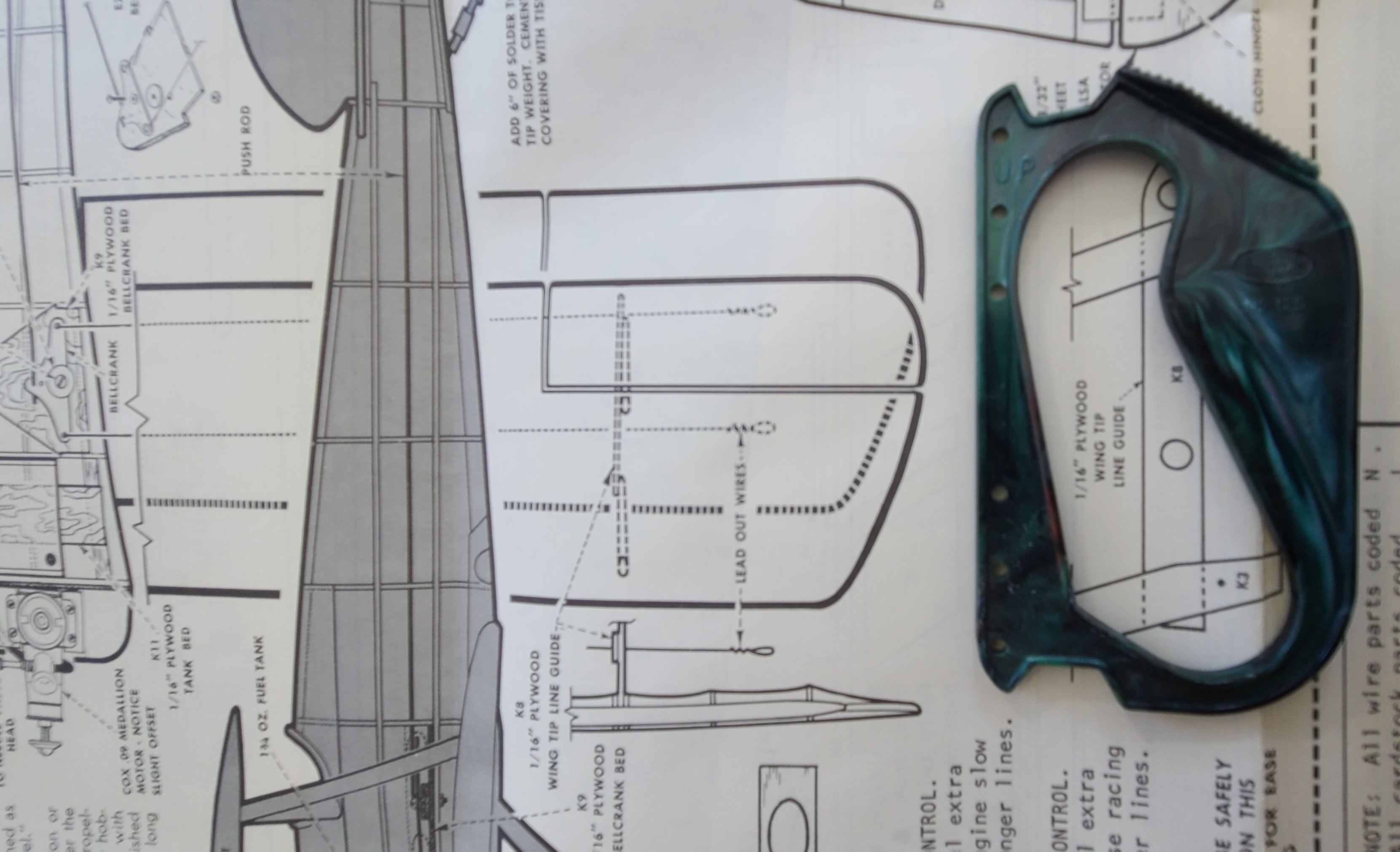
This confused me because there is a control horn and control rods, but only for an elevator. The hinge ailerons were never intended to be functional, which they will be when I convert this to Radio Control.
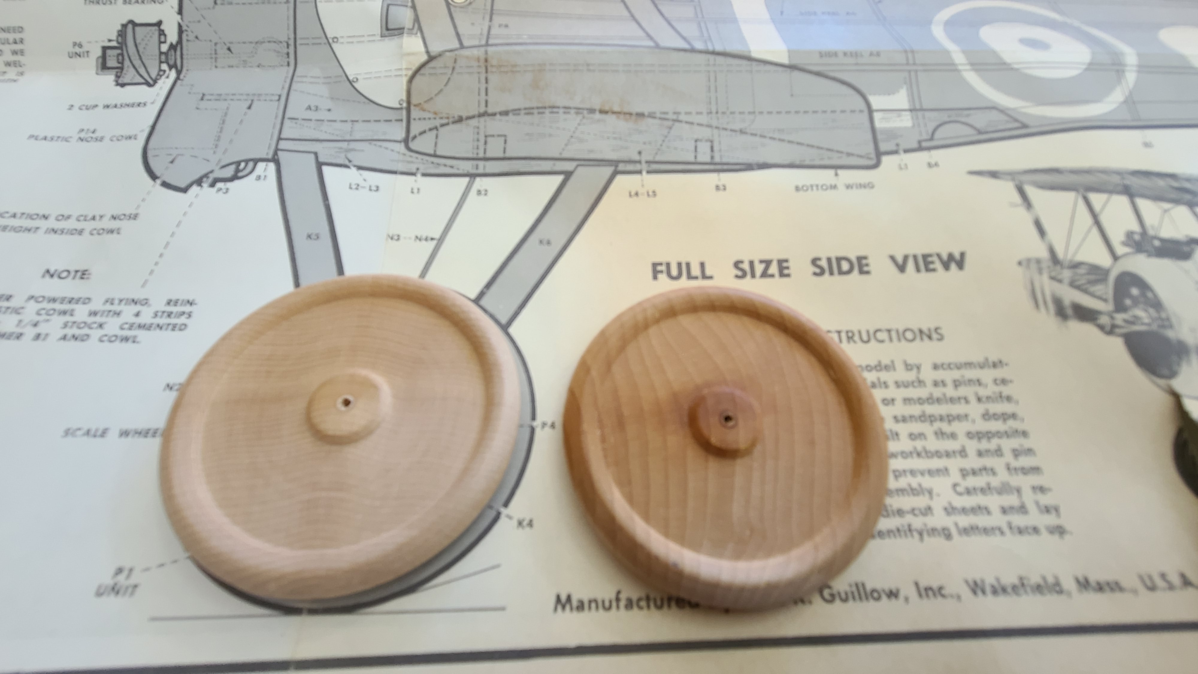
Wooden Wheels
There are some absolutely gorgeous solid wooden wheels included in the box. They seem to be made of some kind of hardwood – maybe cherry (I’m not really sure). They might be a little heavy for a flying model, but they will look great so I might use them, I’m not sure yet.
Errata and other comments on the instructions.
The Guillows instructions and plans are incredibly detailed and generally very complete and accurate, but I’ve found a couple of minor problems, so I thought it might be worth mentioning them in case it helps you.
- I am very sure now that the leading edge of the wings should not be blocked up when building them. I built both my wings by blocking up the trailing edge and rear spar and it “just makes sense” – based on the balsa pieces and the target wing profile. This was proven out by how easy it was to slot the lower wings into the L1 pieces on the fuselage when I got that built. See my video about the wing construction on Tim the Plane Man on YouTube.
- The instructions say to soak the L1 pieces because they need to curve when fitting on the fuselage. This should read L6 – it’s the L6 piece that will be curved and needs to be soaked. Minor typo but important to know.
Credits – other builds of this model
Guillows Kit No – 801 Sopwith Camel
There are a lot of people who have built this model over the years and posted details of their build online. These are some of those I have referred to in doing my build.
radfordc https://www.rcgroups.com/forums/showthread.php?t=305930
Warren Jones https://www.rcgroups.com/forums/showthread.php?t=79733
Bill G http://www.wattflyer.com/forums/showthread.php?t=39480
John Cole https://www.rcgroups.com/forums/show….php?t=2320877
Planning for the Radio Control
This is just some notes. Kind of “thinking out loud” as I read the plans and try to figure out what I need to do to build the plane for RC.
Ailerons
The out of the box plan has moveable ailerons, but only for static display. They are not intended to be functional. So I want to have ailerons and I want them on top and bottom wing. This discussion has gotten so interesting I’ve move it to a separate post which you can find here.
Electronics access
The electronics – receiver (with built in ESC) and 2S Lipo battery will need to go in the front of the plane. Access is going to be a challenge. Even for accessing a battery, let alone if I need to plug or unplug a servo from the receiver for any reason (likely there will be lot’s of reasons). It’s going to be difficult to make the wing removable (as Cliff Harvey did on his Spitfire), because the bottom wing is connected to the top wing. It will be difficult to build an access hatch on the top of the plane (as Tim McKay did on his Zero), so I’m going to do this in 3 parts.
- The battery will go at the front. I’ll build an access hatch in the side of the plane between B2 and B3, but the sliding forward into the front of the plane. The battery I plan to use is a 2S 850 mAh battery that is 52mm x 28m m x 15mm. It will fit nicely across the plane if I build a little shelf where the fuel tank would have been for the glow-plug (gas) engine. The 50g will mostly be in front of the centre of gravity and should mean I may not need any other weight. This will go at the bottom in a shelf between “upper side keel A6” and “lower side keel A8”.
- The receiver (with built in ESC) will also go at the front. This will be in a 2nd shelf above the battery to allow the receiver to connect to the motor. The receiver will at the front of this space between B2 and B3. The receiver I think I’m using weighs 6.4g so if it’s close to directly above the CoG the impact should be negligible.
- I’m planning to install an NX3 Gyro/flight stabilizer to hopefully protect the plane from my amateur attempts at piloting. This must be mounted at the CoG, so in front of the receiver between B1 and B2.
- The servos for the elevator and rudder will probably be mounted upside down between B3 and B4. I’m going to use 3.7g digital servos, and ideally I want to be able to replace these later if whatever I try first doesn’t work. Access to this part is tricky because the space between B3 and B4 is right below the “P13” plastic piece for the cockpit which goes back to B4.
- I’m going to try to make the cockpit/pilot plastic assembly removable and attached with magnets. As I build out the model, this is looking like the best choice.
- I’ve decided to make the P13 plastic cockpit (with guns, pilot and windshield) completely removable. This gives access to the receiver and servos from the top. With some judicious trimming where the P3 slots around the struts and some magnets I can make this work. If I do this, the receiver and servos mount under the pilot and removing the pilot/cockpit assembly gives easy access to everything, but because it’s underneath the main wing, I’m going to have to make the top wing removable (and held on with rubber bands).
Building
This is notes from building. I’m not doing a detailed build log but just noting important things I find as I go.
Wing Blocks
The instructions say to block up the leading edge when building the wings. From what I can see this doesn’t make sense. So I’m blocking up the trailing edge and the rear spar instead. This gives me a much better match with the wing cross section shown on the plan. After building and sanding the lower wing using this approach, I’m very happy with it.
Wing Carbon fiber
I’m adding some 1mm carbon fiber rods to the wings for strength at very little cost in weight. I’ve put one behind the leading edge by putting a groove behind the leading edge and gluing the rod into the groove. I will add a second rod on the 2nd spar that the aileron servos will be mounted to. I decided to do this because I had to trim out a slot in the spar for the servo and that weakened the spar. So having to strengthen it anyway, I decided to take it all the way from the fuselage out to the wing tip.
Covering
The kit comes with some pretty basic white/translucent tissue paper. I am still considering using this, but I have two other options. I like the idea of building a “naked” model with all the structure visible. This is kind of driven by the wheels – if I want to keep those beautiful wooden wheels visible, I think I should do the same with the rest of the model. What holds me back is the electronics, because it will also be visible and that might make a naked model kind of ugly. So I’m also considering:
- Coloured tissue. I picked up some very nice dark green tissue paper from Michaels. I think it might look quite nice and be very close to a realistic look. This is what I am doing.
- I’ve ordered some silkspan. I like the idea of covering in cloth because that’s what (I understand) was used on the real planes. I think it was canvas. So I might try silkspan. I could do a naked model with the silkspan which will mostly hide the electronics, since the silkspan isn’t transparent, or I could paint it. Silkspan will wait for the next build – likely the Dancing Wings Hobby S17 Fokker DR1.
My plan at this point is to build 3 test panels and do the 3 different coverings and see how it comes out. I’ll update when I’ve done that.
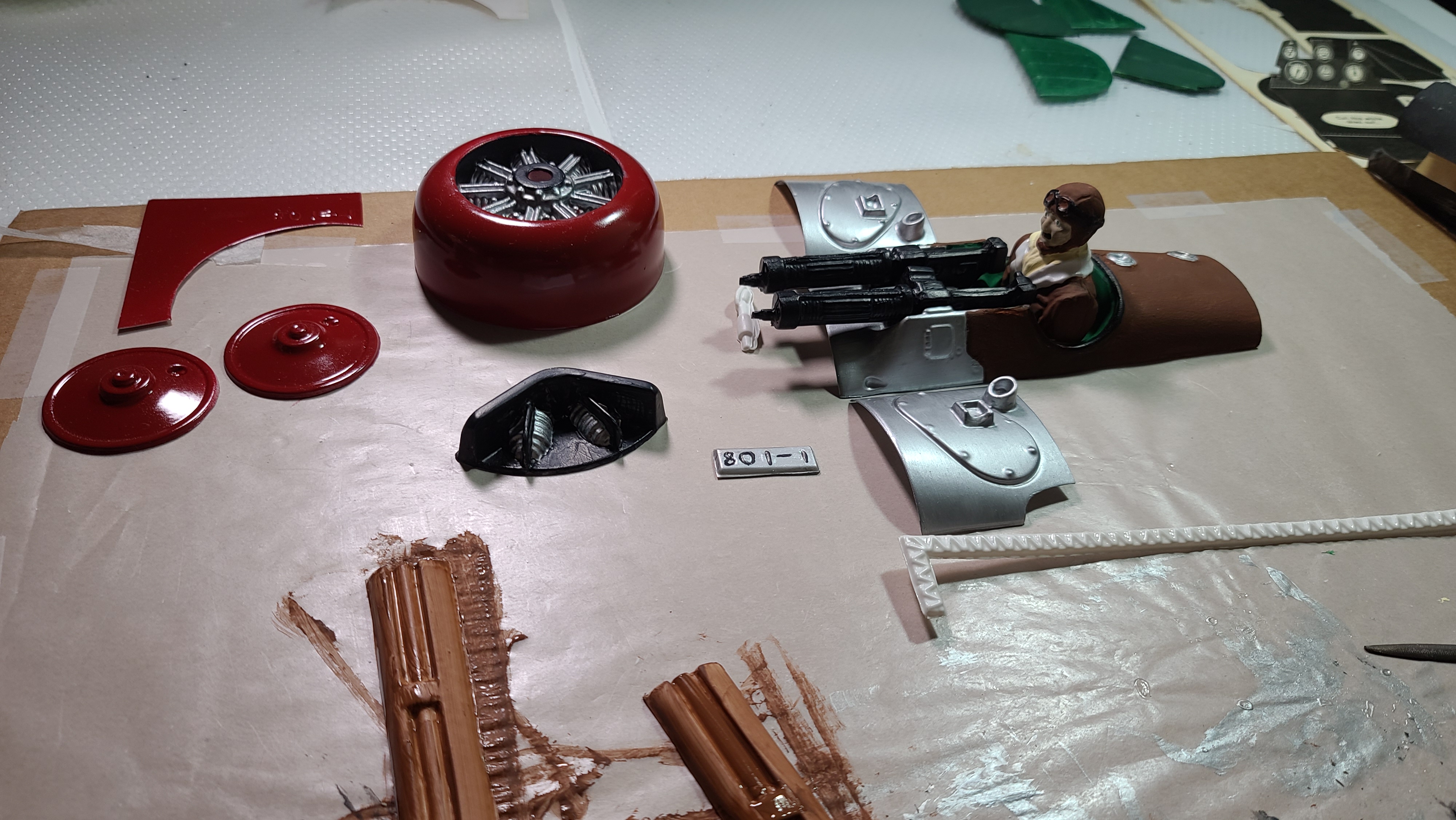
Painting the plastic parts
I agonized over this, but in the end it’s pretty simple. Standard acrylic hobby paint works fine on the plastic parts, but you must do several coats. The first coat will look horrible, streaky, weak. Persist! 2nd coat the plastic will still show through. The 3rd coat will look great.
The one exception was the cowling. I wanted it to look awesome, so I used spray paint. Rustoleum “Painters Touch 2X Ultracover Gloss” colonial red which I bought from Rona. I also painted the wheel covers with this.
Electronics
Specifications
The motor is the 1811-3800KV from Rayspeed RC on AliExpress, the specs say a 5030 prop will produce 205 g of thrust at 7.4 volts and will draw 7.5A. I chose this motor because it weights only 10g, which is crazy because most of the other motors I’ve found that will give me the 200+g thrust I”m looking for weight 20g or more, and weight is critical for this build.
The receiver is the RX444 from AEORC. I bought it off BangGood, but they also have their own site and you can order direct. The RX44x series receivers give you the choice of protocols, so if you want Futaba get the RX442, if you want DSMX its RX444, FrSky is RX445 for the D16 and RX447 for the D8. This receiver has a built in 2S 15A brushless ESC, so I save even more weight here. The receiver weights 7.1g and I don’t need an ESC, probably saving another 5-10g. The 15A ESC is more than double what I need to power the motor.
I am planning to use a flight stabilizer to try to protect the plane from my inexperience as a pilot. I’ve ordered the Radiolink Byme-A from AliExpress, which has good reviews as a flight stabilizer, but importantly weights only 4.5g.
I am using 2x 1.7g AFRC D1302 digital servos mounted in the wings (see my detailed post about this here) for the ailerons. My initial plan is to only put working ailerons on the lower wings. If I find I need more authority on the ailerons, I’ll think about putting them in the upper wing too. This saves at least 10g.
The rudder and elevator are controlled by 2x 3.7g digital servos I bought from Wishiot on Amazon. I don’t think I need servos this big, but I’m kind of going overkill just in case the aileron servo experiment doesn’t pan out. These awesome little digital servos generate 0.5 kg/cm torque which should be about 5x what I need. Saved 10g compared to using “standard” 9g servos.
The battery is a HHZ brand 2S 7.4V 850mAh 20C LiPo from Amazon. It weights 50g which is about the heaviest thing on the plane. If I need to save more weight, this will be the place to do it, but I’m starting with this targeting 185g for the total weight of the plane, with an absolute top limit of 200g.
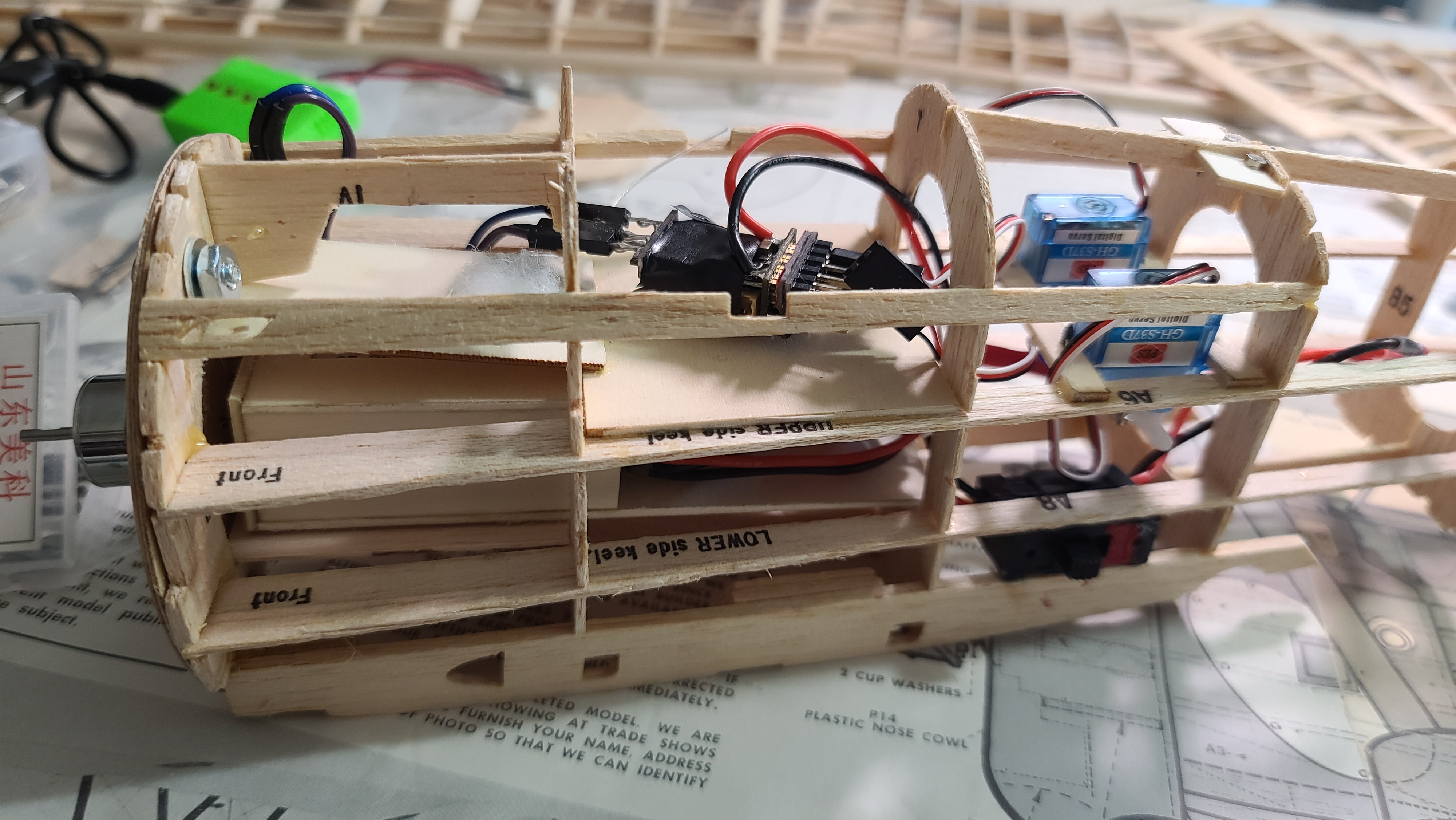
Installation
The motor is screwed directly on the plywood firewall. It fits perfectly and the drive shaft protrudes out through the cowling with just enough room to mount the prop. I added a washer under one of the mounting arms to give (I hope) about 5 degrees down thrust and right thrust.
The receiver mounts at the top of the fuselage under the removable cockpit/gun mount/pilot piece, at the very front between B2 and B3. I’ve left a space between B1 and B2 for a gyro/stabilizer to be mounted at the CoG.
The elevator and rudder servos are mounted behind the pilot between B4 and B5. I found that to get the control rods to run cleanly and fairly straight, it made most sense to mount them upside down. Access will be from below, so I need a new hatch on the bottom between B4 and B5.
The aileron servos are mounted in the wings. I explain this in detail in this post.
I built a battery box, so that I could slide the battery in from an access hatch on the side of the plane between B2 and B3, but then slide it forward so it actually sits under the receiver at the very front of the plane between B1 and B2. I’ve made the box positon adjustable using velcro, so I can move the battery back if necessary to adjust the centre of gravity.
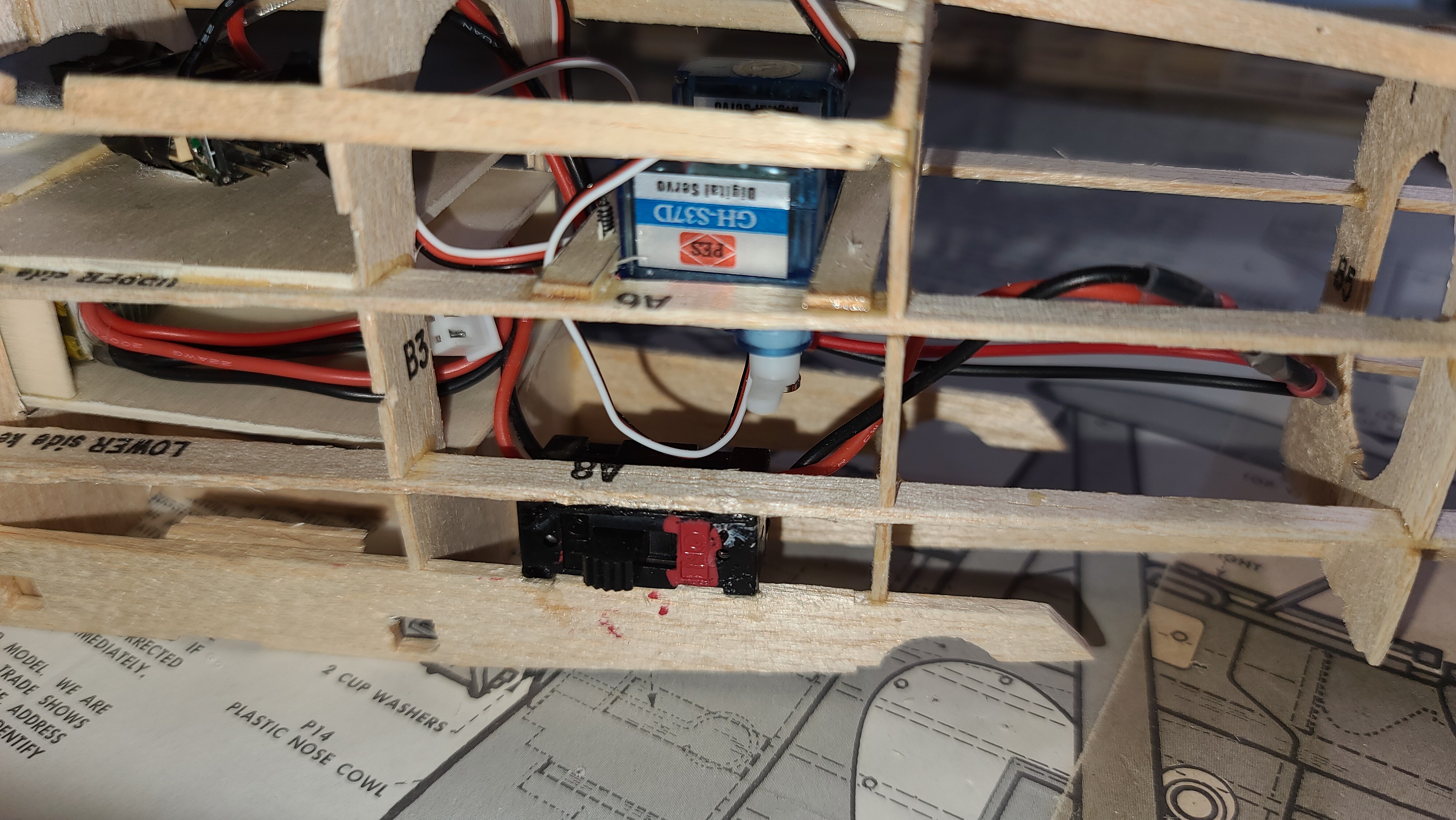
I have installed a switch for the power. Because installing the battery is a bit fiddly, I want to be able to slide the battery in, get it seated and then close the hatch before powering up the electronics. I’ve ordered some pre-wired switches from BangGood, they come with JST style plugs that will plug directly into the power wires on the receiver and the battery with no soldering required, I love that! Here is a picture of how the switch looks:
Assembly
So I’ve started putting everything together and I’m learning some interesting things.
- Using Lego (again) to block up the wings for the dihedral worked great. The wings needed to be be 1″ higher at each end. Using lego worked great.
- Once I put the lower wings in, getting the struts right was a royal pain in the ass. They are so fragile and difficult to align. I ended up building a template mounting for the upper wings that I thought I would use to mount them on. It worked great for lining up the struts, but wasn’t actually necessary once I had everything in place.
- I used 0.8mm carbon fibre rods as the “bracing wires”. Not only do they look great, they also provide a structure for the struts that holds them in the correct place when the upper wing is off. I love carbon fibre.
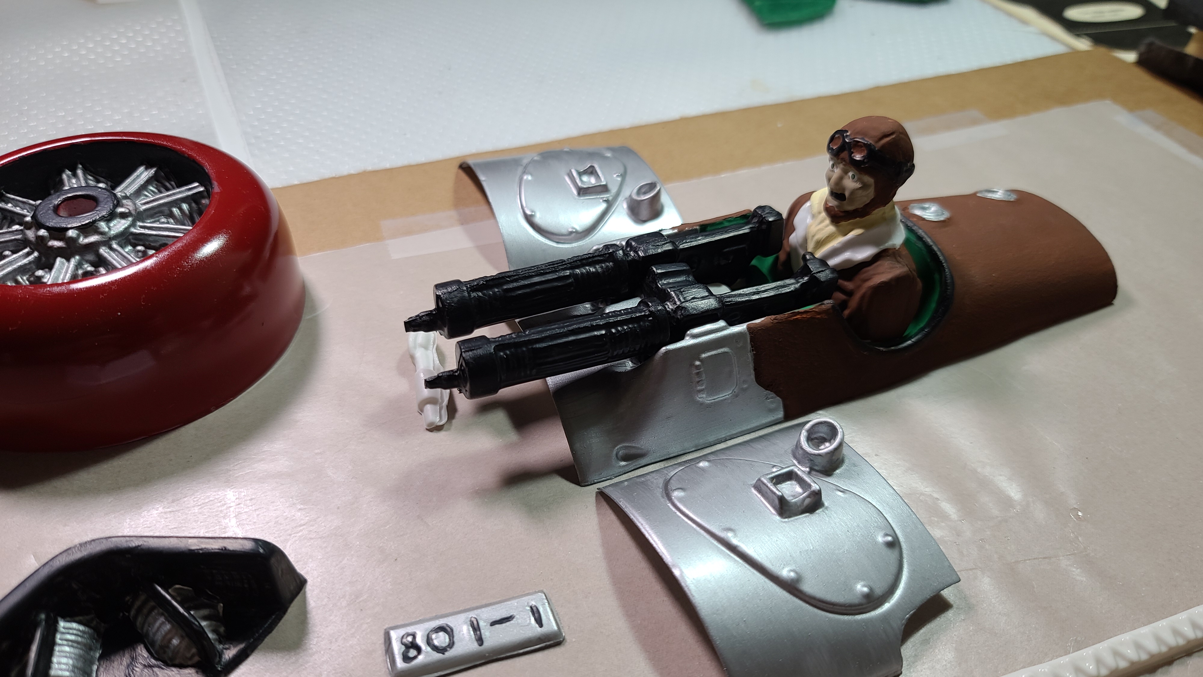
- The pilot is too big. Some people on RC Groups have said the same, the pilot is not to scale and is too big for this model, likely should be about 3/4 or even 2/3 of his current size. This meant that installed as (I think) I was supposed too, his head hits the upper wing. I had to cut out the bottom of the cockpit so I could mount him lower.
- This was a problem because the receiver is mounted right under the pilot, so I couldn’t push him down too much without hitting the receiver. I reached a happy medium. It might have been better to leave him out altogether, or replace him with something a more realistic size. Next time!
- The cowling went on perfectly with the “ring” that I built following Cliff Harvey’s suggestion. It sits perfectly (I think), although I haven’t put the prop on, but it’s about time to try that.
- The upper wing and lower wing line up pretty well, and have pretty much the same angle of incidence, which everyone seems to say is important, but the horizontal stabilizer doesn’t. While the main wings have a slight up angle, the horizontal stabilizer does not, which means the angle of incidence is different to the main wings by .. wait for it .. just under 5 degrees. Now some people seem to say 5 degrees is where you should be worried. Well I’m worried, just looking at it doesn’t look right. And this is based on how the plans look. So I’m going to sand down the mounting area for the horizontal stabilizer a bit to bring it down.

Pingback: Aileron Servos on my Guillows Sopwith Camel | timtuxworth
Did you ever fly this model???? Did your engine choice work out and did your ailerons work out. I just purchased this kit and am planning on doing the same thing!!!!