I spent my 3 day long weekend getting the Pixracer to work. For some reason it made me think of the classic Robert Redford movie “3 Days of the Condor”, where a CIA research analyst who “just reads books” had to figure out a complex conspiracy in 3 days.
Ok, so this is not that, but I was under the pump, I really thought it would be easy, I was planning to get the Pixracer wired up and flashed on Saturday, then work on my Sopwith Camel build for the rest of the weekend. It didn’t work out like that.
But, in the end – I got it working, 3 long days later!
I recorded the whole saga, so come along for the ride! (please Subscribe to Tim the Planman on YouTube for updates). These are the links to the videos:
Maybe my problems are partly because I use a Mac. Why is the Mac “second fiddle” for things like this? Mission Planner has no official version available for Mac. The new release (thanks ArduPilot), still has this caveat:
Native MacOS and iOS support is experimental and not recommended for inexperienced users. For MacOS users it is recommended to use Mission Planner for Windows via Boot Camp or Parallels (or equivalent).
It looks horrible, the fonts are too small to be readable on my laptop screen (I put it on an external monitor when I’m at home, but this won’t work in the field)
None of the panes are resizable
It doesn’t seem to be able to flash the Pixracer. I had to use QGroundControl to do this (worked great).
I don’t know why I should have to use BootCamp or Parallels
But my challenges getting it all working were not just about the Mac.
There is a lot of folklore about flight controllers and how to get them to work, and not a lot of useful documentation. Most of the best information came from getting tidbits of information here and there, from various videos from people like Painless360, Joshua Bardwell and Andrew Newton. But even then – I had to pay attention, it was one 2 second soundbite from one of Painless360’s videos that gave me the hint about why the servos didn’t work while I was running the Pixracer off the power from the USB.
That said there is some useful information out there. Here are some useful links:
The link to the GitHub build where you can download the Mission Planner application package, and this is the link to the 402 build tagged as “beta” – maybe this means it is moving towards a production release? Scroll down to the “artifacts” to download the compiled package for iOS (iPhone) and OSx (Mac).
I’ve learned a few things (as at 2021 August) as I’ve been getting back into building balsa model planes, and getting into radio control flying those same planes. This is a simple checklist for a new model, based on lots of accumulated online wisdom, and the many mistakes I’ve already made in less than a year of this excellent adventure.
Check the centre of gravity. Double check it, triple check it and check it again every time you make even the slightest change to the model.
Err on the side of front heavy vs tail heavy. As Cliff Harvey says – a front heavy plane will fly, a tail heavy plane won’t fly.
Check the horizontal balance. Make sure the plane isn’t heavier on one side or the other. Balance it with weight on the wingtips if necessary.
Make sure the servo arms and control rods are moving freely and not catching on anything inside the model.
When setting up your model in the transmitter:-
Set up a throttle cut switch
Set up failsafe
Set up a flight timer. Start with about 50% of expected flight time, extend it as you learn the model.
Check the controls work the right way. Reverse if necessary in ‘outputs’ (OpenTX)
Check the throw on all control surfaces and use the transmitter to drop it back if necessary (by setting the “weight”).
Put some low rates and expo “options” on a 3 position switch, so you can easily adjust them while flying. For example set up 20%, 30% and 40% expo depending on the switch.
This is just the starting point for the maiden flight. Once you figure out the correct rate and expo based on actually flying behaviour, set it as the default for the model.
If you have ailerons, add a mix to add in some rudder (maybe 10-20%) with the ailerons to make turning easier.
Check your connections. A loose wire can pop in flight, you don’t want that.
Make sure your landing gear is solid (not loosened in the last flight?). Check the wheels are spinning freely.
Check the motor is firmly attached (not loosened in the last flight?)
If the wings are held on by rubber bands, make sure they hold firmly. Add more bands if necessary.
If you have a tail dragger, make sure there is enough clearance so the rudder isn’t dragging. This might look fine in the hanger, but watch out for long grass that might catch or even break the rudder. Check the rudder is solid.
Make sure your battery is fully charged before flying. Double check it with a battery tester.
Turn on your transmitter first – make sure the right model is selected.
Check all controls are working correctly. (ailerons, rudder, elevator, motor)
Enjoy!
Some other tips:
Don’t sweat the small stuff. It’s the big ticket items that impact the model weight.
Covering, electronics, battery!
I saved more than 20 grams on the weight of my Guillows Sopwith Camel 801 by using small (1.7g x2 and 3.7g x 2) digital servos rather than “standard” 9g servos. I don’t think I could save 5 g by spending hours shaving off balsa from the wing ribs, trailing edges, keels and formers.
Test the electronics at every step – from before they go in the plane.
Build in the electronics as you go. Trying to add them in at the end, even with a well designed kit, is fraught with challenges. Continue testing as you build up the plane around the electronics.
Try to add access to the electronics. You will probably need to fix or replace or check them many times.
Strengthen weak points on the model using carbon fiber. Good places to look are undercarriage, wings, and where the wings connect to the fuselage. If it’s a biplane strengthen the struts, especially where they connect to the wings.
Put some down thrust angle and right thrust angle (for a front mounted “puller” model) in for the motor to counteract the centrifugal force created by the motor, likely about 5% right and 5% down. This is especially important for outrunner brushless motors.
Always take off the propeller when messing with anything electronic with a battery connected.
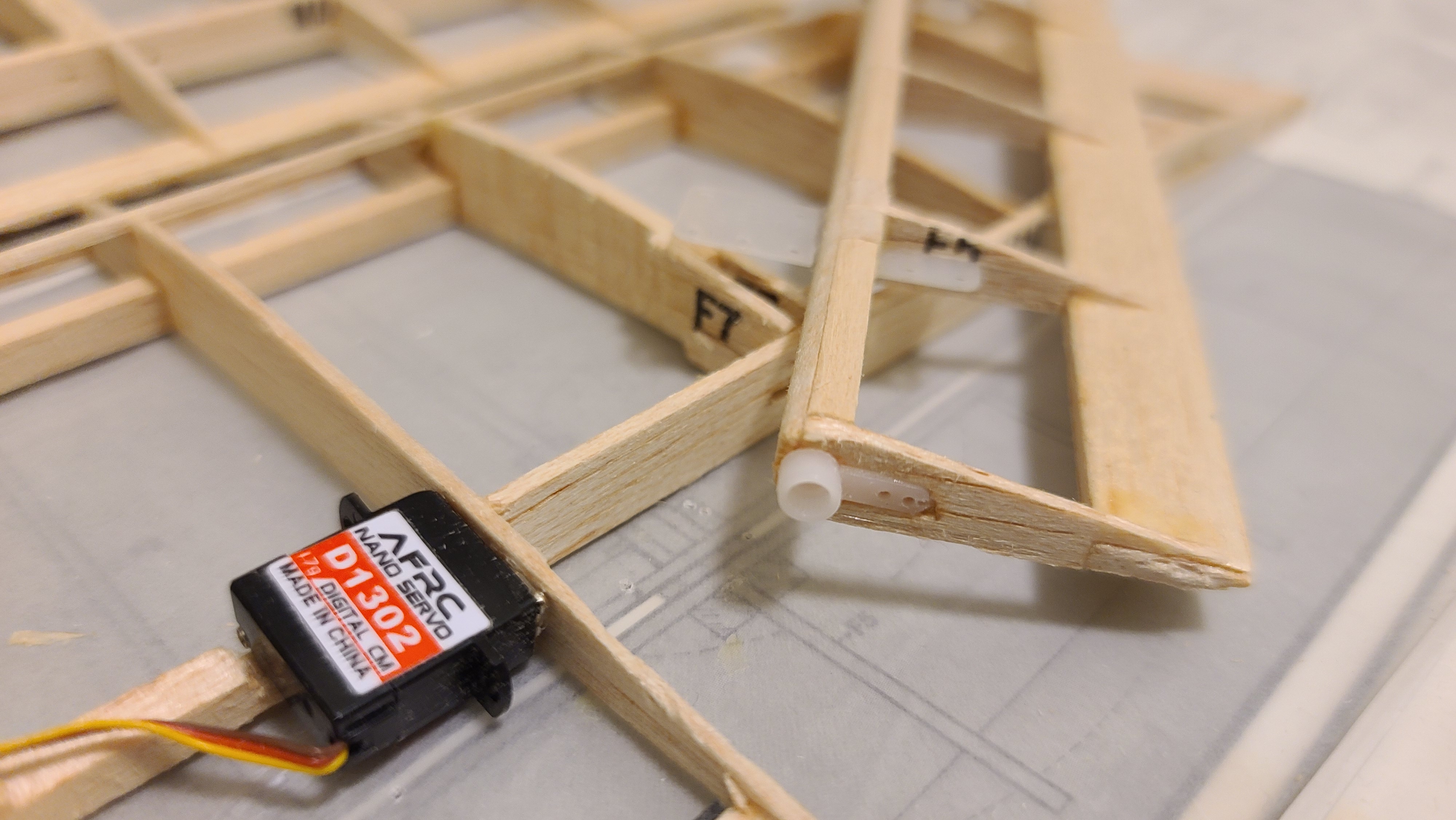
Figuring out the aileron servos for the Guillows Sopwith Camel 801 build (see the post about the build here) has been a very interesting journey. So I’ve created this separate post to write up just the ailerons. Hope it helps.
Direct Drive mounting of the Aileron servoShowing how the servo arm is built into the edge of the aileron.
The out of the box plan has moveable ailerons, but only for static display. They are not intended to be functional. So I want to have ailerons and I want them on top and bottom wing.
Both Cliff Harvey with his Guillows Spitfire, and Tim McKay who had a similar experience with the Guillows Zero, pretty much proved that the control of ailerons is going to be essential to making this plane behave nicely when it flies. So I have to solve two problems 1. Getting ‘control’ out to the end of the wings. 2. Getting the control up from the bottom wing to the top wing.
First I’m going to mount servos out on the wing. I’m actually thinking that because this is a biplane which will have 4 ailerons, the torque required for each of them is much smaller as its divided by 4.
So I’ve been doing more thinking and shopping and found some absolutely amazing tiny 1.7g AFRC D1302 digital servos that have torque of 0.15 kg/cm (0.014 Nm) which is exactly what is required for ailerons of this size according to at least 2 different surface area/torque calculators I have found online.
So I am going to do an experiment – using direct drive of the ailerons using these wonderful little digital servos.
Calculations
Trying to figure out exactly how much torque is actually required for a servo isn’t easy. What seems to have happened is that many years ago someone figured out that a 9g servo was “good enough” – and was pretty light compared to the weight of other components so everyone just kept using 9g servos.
But like most other areas of technology in this ever-changing world we live in, the technology of servos is improving in leaps and bounds. This is being driven by other uses of servos such as robotics. To me this means it makes sense to ask two simple questions:-
How much torque is required for a particular purpose?
What is the smallest servo I can use to give me that torque?
For the Sopwith Camel, I have a target weight in mind of 180g. If I don’t meet that, the absolute worst case I want is < 250g. This means weight is important, and if (for example) I can shave off 20-30g or more by switching out 4x or even 6x 9g servos for some much smaller digital servos, I’m all for it.
I did a lot of research (i.e. Googling) about this, with not a lot of results. I have basically found 2 web sites that seem to have usable and understandable formulas for calculating torque.
There is a calculator at Radio Control Info. This is ok but doesn’t explain its formula, so I am suspicious of it. I use it to validate my own calculations. This one is also very strange as it asks for all the input parameters in metric and then gives the results in “oz-in”. This is confusing and annoying.
Minnesota Big Birds has a page with a fully documented torque calculation formula by Chuck Gadd. I love this. The rational and mathematics are out there in the open and explained and I can put this into spreadsheet and do my own calculations and even tweak it. This is their formula:
Of course this is also frustrating because it uses “Miles per hour” (remember miles? – something from the old British Empire I think), and gives the results in oz-in instead of Nm or even kg-cm. But having the formula it’s pretty easy to update it to use modern metric units. Miles/hour to km/hour is easy – Just need to multiply by 0.621371^2, so that just changes the constant at the front. The result can be converted to km-cm by multiplying by 0.07200778893234 or 0.00706155 to get Nm which is actually the proper metric unit for torque. Most servos are sized in kg-cm (or oz-in, I’ll ignore that), so the new formula is
Lastly there is a pdf thoroughly documenting servo torque requirements by Andy Meysner of the Southern Ontario Glider Group, which is the one I like the best so far. It refers to the other two, but this explains how the formula works in details and it calculates using metric inputs, and gives the results in Nm. as it says:
Servo torque is usually specified in oz-in or kg-cm. To obtain the torque in oz-in or kg- cm, multiply the result in N-m by 141.6 or 10.2 respectively
The whole formula assuming a servo arm, control rod and control horn on the control surface is:
Ts = V2 x L x C2 x sin(αh) x tan(αh)/ (4 tan(αs))
(assuming Cd – drag coefficient = 1.0 and p = 1.2. Read the article for details)
V = Airspeed in m/s (multiply km/hour by 0.277778)
L = Length of the control surface in meters (3.5 cm = 0.035 meters)
αh is the rotation angle of the control surface from neutral in degrees
αs is the rotation angle of the servo arm in degrees measured from the servo arm position at 900 to the pushrod – I’m assuming αh= αs (I hope this is valid but I think it should be)
But here is where it gets interesting, Andy’s article also explains in detail how the calculation is done and as part of the calculation, it shows the calculation for the torque on the control surface itself as an intermediate step. This is fascinating because this would be the torque required for a direct drive servo like the one I plan to use on the ailerons on the Sopwith Camel. The formula for this would be:
T = ((Cd ρ V2 C L sin(αh))/2) C / 2
(again Cd = 0, p = 1.2)
Note that C appears multiple times, so this can be simplified to
T = ρ V2 C2 L sin(αh)/4
For the ailerons of the Sopwith Camel, which has:
Chord = C = 3.5 cm or 0.035m
Length = L = 14 cm or 0.014m
Speed = V = 50 km/hour (I’m making an assumption here)
Control surface deflection = servo deflection = 20 degrees
So the results for the Sopwith Camel ailerons are:
Torque kg-cm: 0.14 – which is less than the 0.15 spec for the 1.7g digital servos I’m using
Interestingly I did the calculations for the all the control surfaces and this is the result:
Surface
Chord
Length
Deflection
Speed Km-hour
Torque [Big Birds]
Torque [Meysner]
Ailerons
3.5 cm
14 cm
25 degrees
50 km/hr
.043 kg/cm .004 Nm
.044 kg/cm .004 Nm
Elevator
3 cm
18 cm
20 degrees
50 km/hr
.088 kg/cm .008 Nm
0.033 kg/cm .003 Nm
Rudder
4.5 cm
8 cm
20 degrees
50 km/hr
.087 kg/cm 0.008 Nm
.035 kg/cm .003 Nm
[I’m not sure why there is such a discrepancy between the Big Bird and Meysner numbers for elevator and rudder while the aileron numbers are so similar. I think I might have an error in my spreadsheet somewhere – more digging required].
This was a very long winded way to show that the 0.15 kg/cm digital servos at 1.7g that I plan on using, have approximately 3X the required torque for the Sopwith Camel ailerons!
It also means that I should probably be able to use the same 1.7g servos for elevator and rudder, although I had been planning to use some 3.7g servos I have for those controls. I’m not sure what I will do about that yet (2021-07-30).
Installation
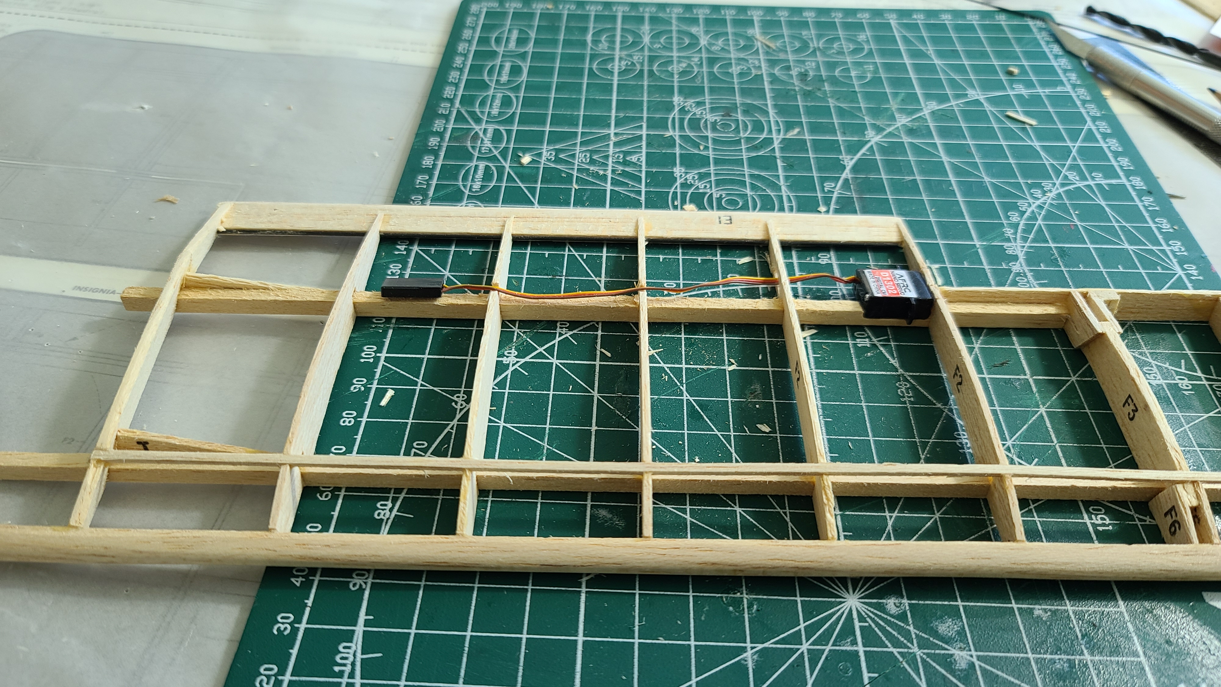
I’ve started installing the first of possibly 4 aileron servos directly inside the wing next to the ailerons. They will be direct drive which cuts out a lot of weight and inefficiency. These will be 1.7g digital servos. It seems to make sense. See my YouTube video that shows how it works.
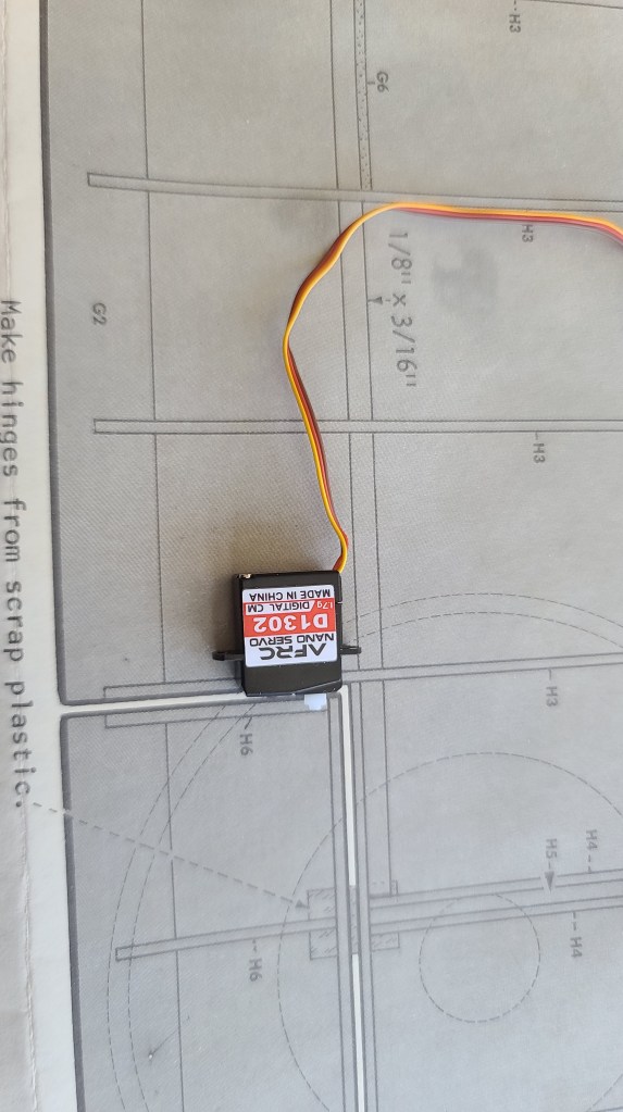
Wires
Running the wires from the aileron to the fuselage is an interesting challenge. I see most people end up putting holes in the middle of the ribs. It struck me while I was doing this that I was weakening the weakest part of the rib by doing this. Why not, I thought, run the wires along the spar, which is the strongest part of the wing, and would make for the easiest place to run the wires while also making them less visible if I use tissue paper for the covering (which I haven’t decided on yet). This is how it looks.
The next thing is to figure out how to connect the wires to the receiver. I had been planning to have 2 channels and a Y cable on each channel, a bit like running a 2 channel mix driver for ailerons on a single wing plane, but using the Y to split the signal so the upper and lower wing each get the same signal.
Rob Mawer on the Guillow’s Facebook group suggested another option – use 4 channels with separate wires to each servo. This wouldn’t add much more weight, but would make it easier to centre and trim each servo if they are on separate channels. It makes the model setup in the transmitter a little tricky, but with OpenTX, it should be doable. Right now I’m thinking of this as a backup plan, but that might change when I build the upper wings. Stay tuned!
Upper wings
Well I thought the upper wings were going to be easy. Just use a Y connector to drive the upper wing from the same receiver channel as the lower wing. I would do a 2 channel aileron mix in the Jumper T-Lite, OpenTX makes it so easy. But after I posted on YouTube and Facebook, this was the first thing people called into question.
Rob Mawer on Facebook groups pointed out that centering and trimming the two ailerons might be tricky if the two ailerons were not exactly aligned. He suggested using a 4 channel design so each servo could be centered and trimmed separately. The OpenTX setup would be very custom, but doable.
This also makes me think that using the Y to split the signal on the same side might not be as smart as running the upper wings with one Y on one channel and then the lower wings on a second Y on a second channel. This would mean the ailerons are centered and trimmed as per a normal single channel arrangement, but it would have to be done twice, once for the lower wings and once for the upper wings. I kind of like this idea.
Cliff Harvey RC Planes on YouTube suggested that ailerons on the upper wings might not even be necessary, the ones on the lower wings might be enough. I’m definitely drawn to this idea, it makes things much simpler.
Irwin Weisbrot on YouTube suggested that I could mechanically link the lower aileron to the upper which would mean I would not need a servo in the upper wing. This is attractive since it is very similar to how the real plane was built, and if I got it right it would look very “scale”, but it would double the thrust that the servo would be working against and therefore the amount of torque required. My calculations right now have a lot of ‘fudge factor’ and the two different methods give so different results, that I’m not convinced this would be safe. I might keep this in my back pocket.
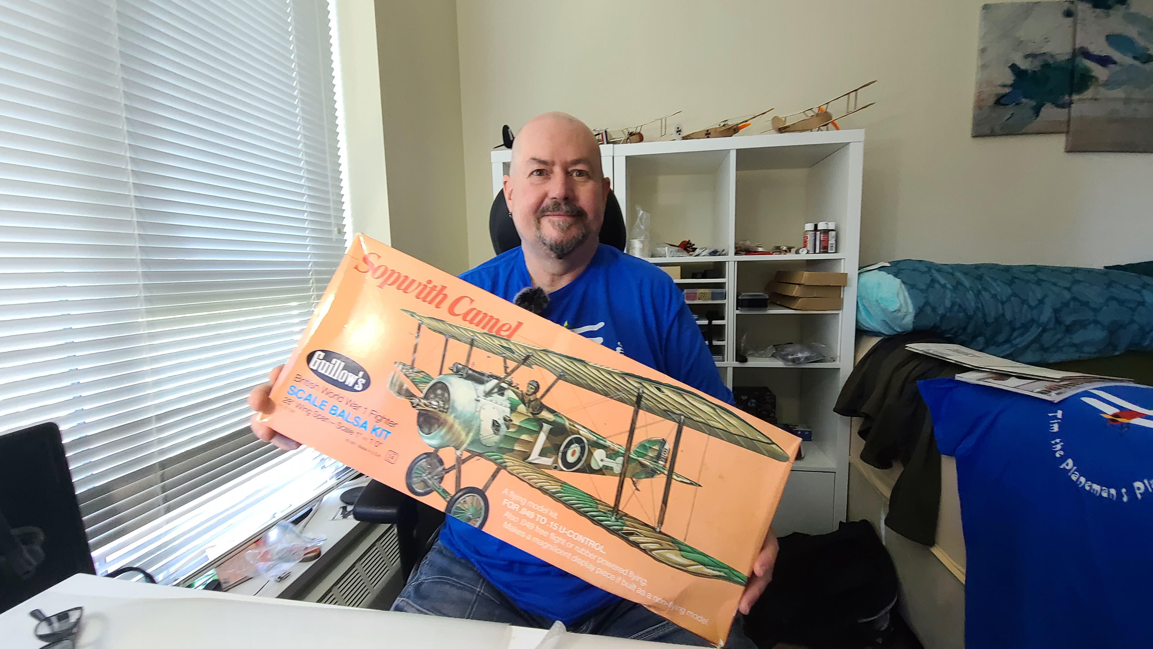
I just opened [20 June 2021] my “new” Sopwith Camel kit from Guillows. I say “new”, but I bought this off eBay because at the time I ordered it, the Guillows website was Out of Stock. So the “new” kit I bought from eBay is actually pretty old. It’s well preserved, but the paper is yellowing and the box doesn’t have the “Laser Cut” sticker that the new models have. So this model is die-cut, the old way, pre the modern days of laser cut balsa.
This is quite fun because some of the things included in the box are things you will never see any more. Like a paper order form for ordering replacement parts by sending the form and a cheque (remember cheques?) to Paul K. Guillow Inc. Box 229, Wakefield, MA, 01880.
The copyright notices on the plans and the enclosed catalog say 1973 and 1974. The stamped model number on the kit pieces say “801-1”. I can’t be sure but I think this kit is about 50 years old.
Luckily all of the wooden pieces are well preserved, except for the plywood containing some of the slats and frame pieces which is a bit warped. I’m soaking this in water and trying to dry it flat. This worked out fine.
Review of Instructions
Having opened the box, the first thing I did was read the instructions. There were some very interesting things in these instructions, not all relevant to building the plane, but I thought I’d just note them as I go.
Copyright 1973
The copyright on these plans is 1973, and the copyright on the little “Catalog” included in the box, is 1974. Now this doesn’t prove the kit is that old, but it is certainly interesting. I haven’t found anything dated more recently than 1974.
It’s also very interesting that included in the kit was an “order form” for ordering replacement parts.
U-Control
The kit is made for rubber powered free flight or “U-Control”. I didn’t know what that was, but I did figure it out. It is what used to do when I was a teenager building and flying “control line” planes – flying around in a circle controlled by wires and a little handle. You tilt your hand to make the plane go up and down. The kit even includes the handle (but no wires) and I didn’t know what it was at first. It’s for control line flying!
This confused me because there is a control horn and control rods, but only for an elevator. The hinge ailerons were never intended to be functional, which they will be when I convert this to Radio Control.
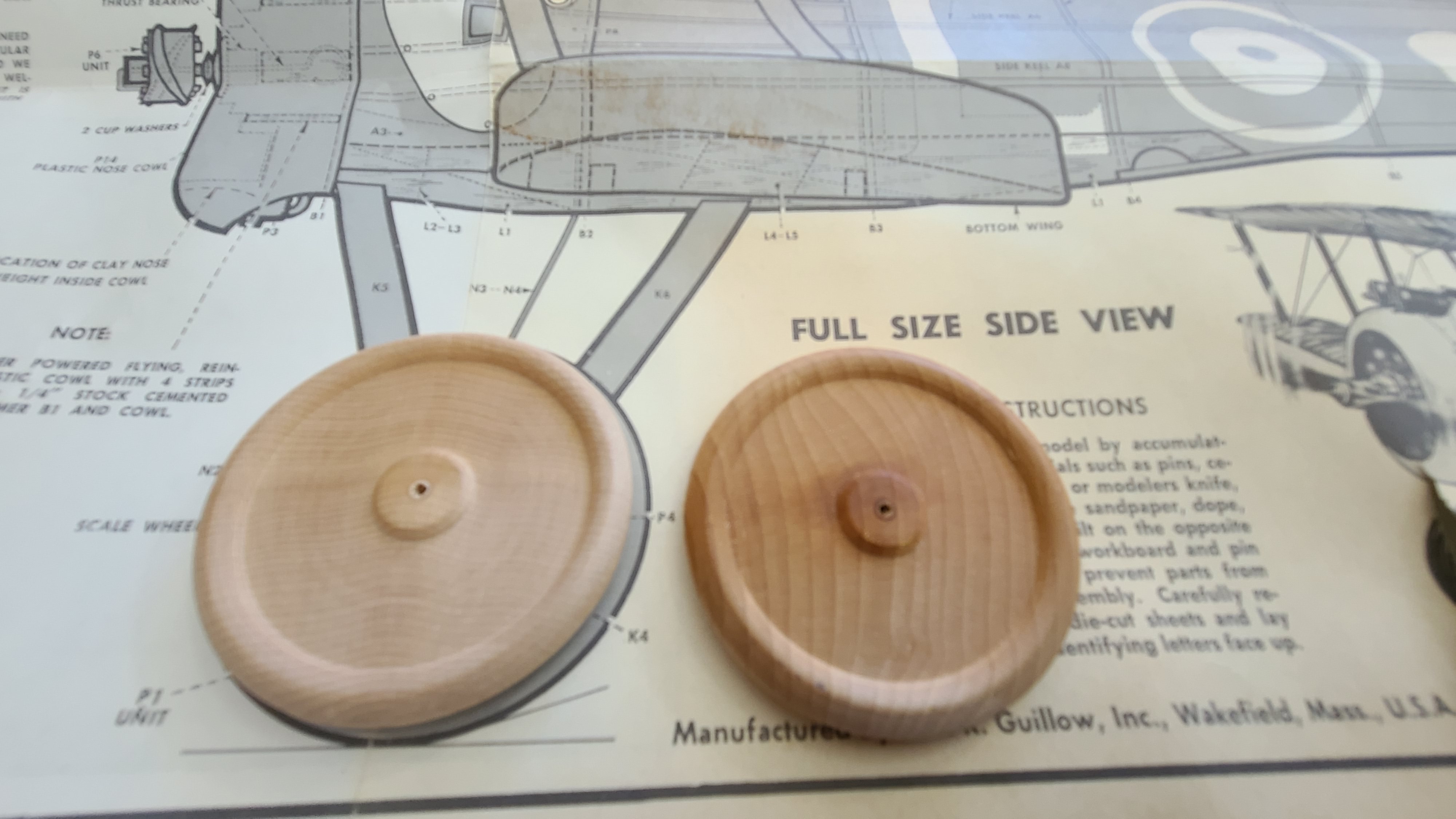
Wooden Wheels
There are some absolutely gorgeous solid wooden wheels included in the box. They seem to be made of some kind of hardwood – maybe cherry (I’m not really sure). They might be a little heavy for a flying model, but they will look great so I might use them, I’m not sure yet.
Turned wooden wheels out of the box
Errata and other comments on the instructions.
The Guillows instructions and plans are incredibly detailed and generally very complete and accurate, but I’ve found a couple of minor problems, so I thought it might be worth mentioning them in case it helps you.
I am very sure now that the leading edge of the wings should not be blocked up when building them. I built both my wings by blocking up the trailing edge and rear spar and it “just makes sense” – based on the balsa pieces and the target wing profile. This was proven out by how easy it was to slot the lower wings into the L1 pieces on the fuselage when I got that built. See my video about the wing construction on Tim the Plane Man on YouTube.
The instructions say to soak the L1 pieces because they need to curve when fitting on the fuselage. This should read L6 – it’s the L6 piece that will be curved and needs to be soaked. Minor typo but important to know.
There are a lot of people who have built this model over the years and posted details of their build online. These are some of those I have referred to in doing my build.
This is just some notes. Kind of “thinking out loud” as I read the plans and try to figure out what I need to do to build the plane for RC.
Ailerons
The out of the box plan has moveable ailerons, but only for static display. They are not intended to be functional. So I want to have ailerons and I want them on top and bottom wing. This discussion has gotten so interesting I’ve move it to a separate post which you can find here.
Electronics access
The electronics – receiver (with built in ESC) and 2S Lipo battery will need to go in the front of the plane. Access is going to be a challenge. Even for accessing a battery, let alone if I need to plug or unplug a servo from the receiver for any reason (likely there will be lot’s of reasons). It’s going to be difficult to make the wing removable (as Cliff Harvey did on his Spitfire), because the bottom wing is connected to the top wing. It will be difficult to build an access hatch on the top of the plane (as Tim McKay did on his Zero), so I’m going to do this in 3 parts.
The battery will go at the front. I’ll build an access hatch in the side of the plane between B2 and B3, but the sliding forward into the front of the plane. The battery I plan to use is a 2S 850 mAh battery that is 52mm x 28m m x 15mm. It will fit nicely across the plane if I build a little shelf where the fuel tank would have been for the glow-plug (gas) engine. The 50g will mostly be in front of the centre of gravity and should mean I may not need any other weight. This will go at the bottom in a shelf between “upper side keel A6” and “lower side keel A8”.
The receiver (with built in ESC) will also go at the front. This will be in a 2nd shelf above the battery to allow the receiver to connect to the motor. The receiver will at the front of this space between B2 and B3. The receiver I think I’m using weighs 6.4g so if it’s close to directly above the CoG the impact should be negligible.
I’m planning to install an NX3 Gyro/flight stabilizer to hopefully protect the plane from my amateur attempts at piloting. This must be mounted at the CoG, so in front of the receiver between B1 and B2.
The servos for the elevator and rudder will probably be mounted upside down between B3 and B4. I’m going to use 3.7g digital servos, and ideally I want to be able to replace these later if whatever I try first doesn’t work. Access to this part is tricky because the space between B3 and B4 is right below the “P13” plastic piece for the cockpit which goes back to B4.
I’m going to try to make the cockpit/pilot plastic assembly removable and attached with magnets. As I build out the model, this is looking like the best choice.
I’ve decided to make the P13 plastic cockpit (with guns, pilot and windshield) completely removable. This gives access to the receiver and servos from the top. With some judicious trimming where the P3 slots around the struts and some magnets I can make this work. If I do this, the receiver and servos mount under the pilot and removing the pilot/cockpit assembly gives easy access to everything, but because it’s underneath the main wing, I’m going to have to make the top wing removable (and held on with rubber bands).
Building
This is notes from building. I’m not doing a detailed build log but just noting important things I find as I go.
Wing Blocks
The instructions say to block up the leading edge when building the wings. From what I can see this doesn’t make sense. So I’m blocking up the trailing edge and the rear spar instead. This gives me a much better match with the wing cross section shown on the plan. After building and sanding the lower wing using this approach, I’m very happy with it.
Wing Carbon fiber
I’m adding some 1mm carbon fiber rods to the wings for strength at very little cost in weight. I’ve put one behind the leading edge by putting a groove behind the leading edge and gluing the rod into the groove. I will add a second rod on the 2nd spar that the aileron servos will be mounted to. I decided to do this because I had to trim out a slot in the spar for the servo and that weakened the spar. So having to strengthen it anyway, I decided to take it all the way from the fuselage out to the wing tip.
Covering
The kit comes with some pretty basic white/translucent tissue paper. I am still considering using this, but I have two other options. I like the idea of building a “naked” model with all the structure visible. This is kind of driven by the wheels – if I want to keep those beautiful wooden wheels visible, I think I should do the same with the rest of the model. What holds me back is the electronics, because it will also be visible and that might make a naked model kind of ugly. So I’m also considering:
Coloured tissue. I picked up some very nice dark green tissue paper from Michaels. I think it might look quite nice and be very close to a realistic look. This is what I am doing.
I’ve ordered some silkspan. I like the idea of covering in cloth because that’s what (I understand) was used on the real planes. I think it was canvas. So I might try silkspan. I could do a naked model with the silkspan which will mostly hide the electronics, since the silkspan isn’t transparent, or I could paint it. Silkspan will wait for the next build – likely the Dancing Wings Hobby S17 Fokker DR1.
My plan at this point is to build 3 test panels and do the 3 different coverings and see how it comes out. I’ll update when I’ve done that.
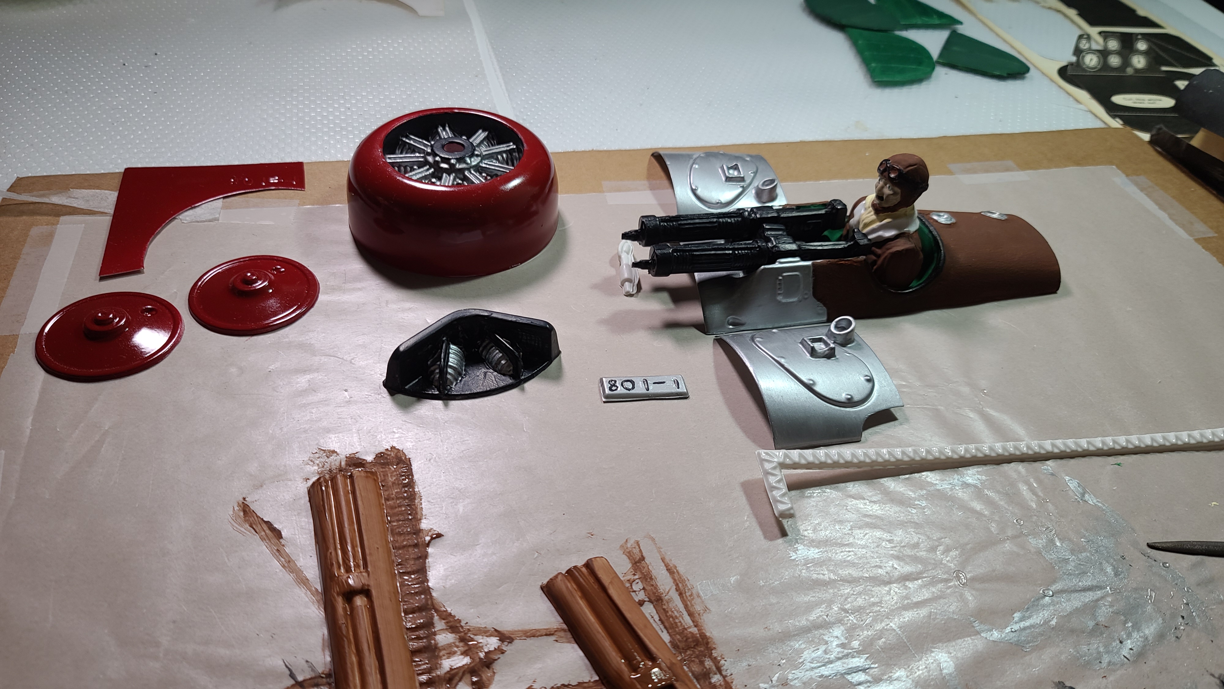
Painting the plastic parts
I agonized over this, but in the end it’s pretty simple. Standard acrylic hobby paint works fine on the plastic parts, but you must do several coats. The first coat will look horrible, streaky, weak. Persist! 2nd coat the plastic will still show through. The 3rd coat will look great.
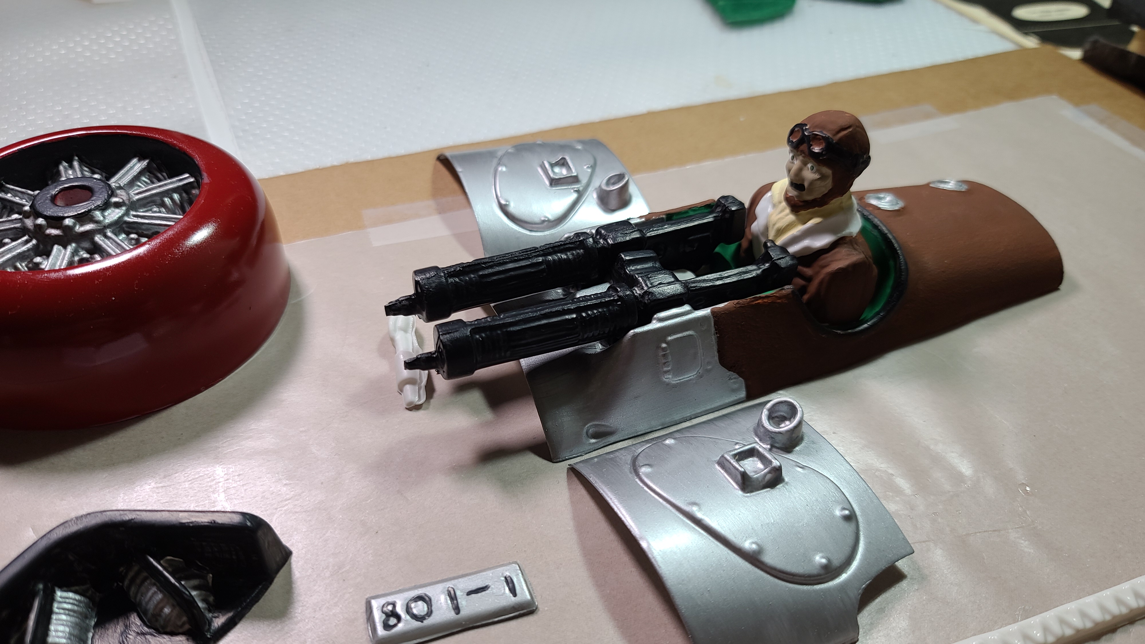
The one exception was the cowling. I wanted it to look awesome, so I used spray paint. Rustoleum “Painters Touch 2X Ultracover Gloss” colonial red which I bought from Rona. I also painted the wheel covers with this.
Painted plastic parts for the Guillows Sopwith Camel 801The cockpit and pilot. I think it looks awesome.
Electronics
Specifications
The motor is the 1811-3800KV from Rayspeed RC on AliExpress, the specs say a 5030 prop will produce 205 g of thrust at 7.4 volts and will draw 7.5A. I chose this motor because it weights only 10g, which is crazy because most of the other motors I’ve found that will give me the 200+g thrust I”m looking for weight 20g or more, and weight is critical for this build.
The receiver is the RX444 from AEORC. I bought it off BangGood, but they also have their own site and you can order direct. The RX44x series receivers give you the choice of protocols, so if you want Futaba get the RX442, if you want DSMX its RX444, FrSky is RX445 for the D16 and RX447 for the D8. This receiver has a built in 2S 15A brushless ESC, so I save even more weight here. The receiver weights 7.1g and I don’t need an ESC, probably saving another 5-10g. The 15A ESC is more than double what I need to power the motor.
I am planning to use a flight stabilizer to try to protect the plane from my inexperience as a pilot. I’ve ordered the Radiolink Byme-A from AliExpress, which has good reviews as a flight stabilizer, but importantly weights only 4.5g.
I am using 2x 1.7g AFRC D1302 digital servos mounted in the wings (see my detailed post about this here) for the ailerons. My initial plan is to only put working ailerons on the lower wings. If I find I need more authority on the ailerons, I’ll think about putting them in the upper wing too. This saves at least 10g.
The rudder and elevator are controlled by 2x 3.7g digital servos I bought from Wishiot on Amazon. I don’t think I need servos this big, but I’m kind of going overkill just in case the aileron servo experiment doesn’t pan out. These awesome little digital servos generate 0.5 kg/cm torque which should be about 5x what I need. Saved 10g compared to using “standard” 9g servos.
The battery is a HHZ brand 2S 7.4V 850mAh 20C LiPo from Amazon. It weights 50g which is about the heaviest thing on the plane. If I need to save more weight, this will be the place to do it, but I’m starting with this targeting 185g for the total weight of the plane, with an absolute top limit of 200g.
Installation
The motor is screwed directly on the plywood firewall. It fits perfectly and the drive shaft protrudes out through the cowling with just enough room to mount the prop. I added a washer under one of the mounting arms to give (I hope) about 5 degrees down thrust and right thrust.
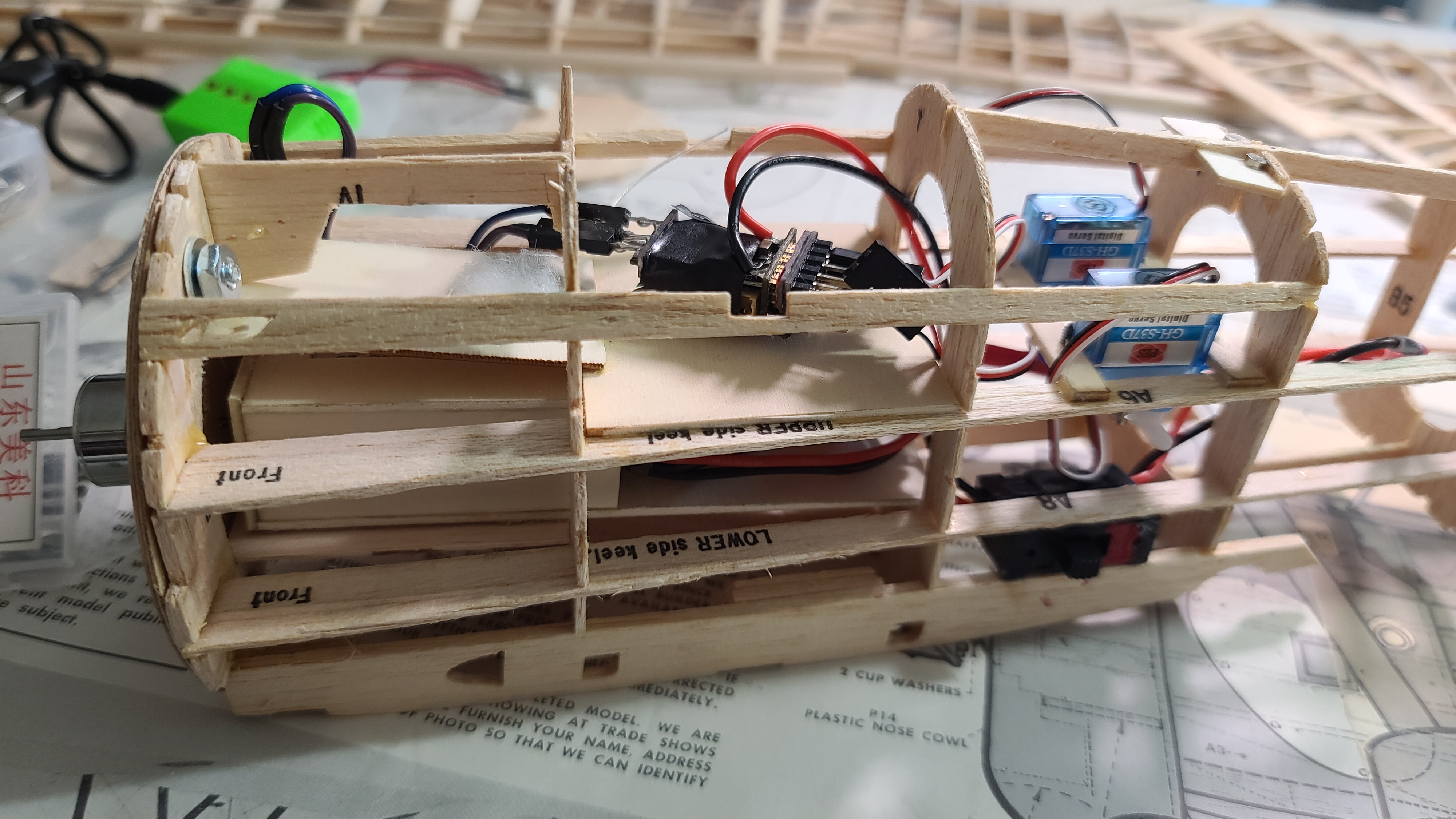
The receiver mounts at the top of the fuselage under the removable cockpit/gun mount/pilot piece, at the very front between B2 and B3. I’ve left a space between B1 and B2 for a gyro/stabilizer to be mounted at the CoG.
The elevator and rudder servos are mounted behind the pilot between B4 and B5. I found that to get the control rods to run cleanly and fairly straight, it made most sense to mount them upside down. Access will be from below, so I need a new hatch on the bottom between B4 and B5.
The aileron servos are mounted in the wings. I explain this in detail in this post.
I built a battery box, so that I could slide the battery in from an access hatch on the side of the plane between B2 and B3, but then slide it forward so it actually sits under the receiver at the very front of the plane between B1 and B2. I’ve made the box positon adjustable using velcro, so I can move the battery back if necessary to adjust the centre of gravity.
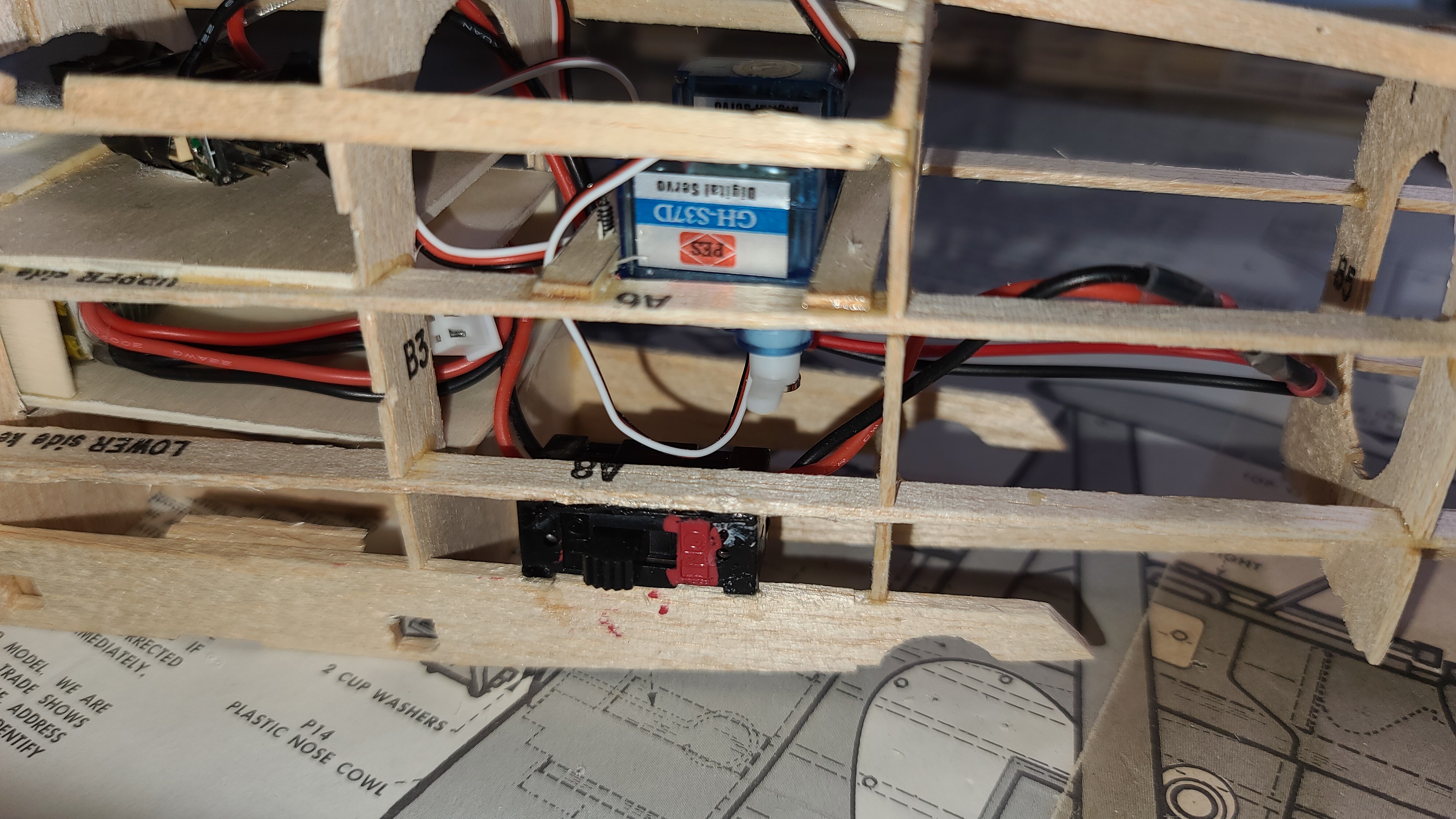
I have installed a switch for the power. Because installing the battery is a bit fiddly, I want to be able to slide the battery in, get it seated and then close the hatch before powering up the electronics. I’ve ordered some pre-wired switches from BangGood, they come with JST style plugs that will plug directly into the power wires on the receiver and the battery with no soldering required, I love that! Here is a picture of how the switch looks:
Assembly
So I’ve started putting everything together and I’m learning some interesting things.
Using Lego (again) to block up the wings for the dihedral worked great. The wings needed to be be 1″ higher at each end. Using lego worked great.
Once I put the lower wings in, getting the struts right was a royal pain in the ass. They are so fragile and difficult to align. I ended up building a template mounting for the upper wings that I thought I would use to mount them on. It worked great for lining up the struts, but wasn’t actually necessary once I had everything in place.
I used 0.8mm carbon fibre rods as the “bracing wires”. Not only do they look great, they also provide a structure for the struts that holds them in the correct place when the upper wing is off. I love carbon fibre.
The pilot is too big. Some people on RC Groups have said the same, the pilot is not to scale and is too big for this model, likely should be about 3/4 or even 2/3 of his current size. This meant that installed as (I think) I was supposed too, his head hits the upper wing. I had to cut out the bottom of the cockpit so I could mount him lower.
This was a problem because the receiver is mounted right under the pilot, so I couldn’t push him down too much without hitting the receiver. I reached a happy medium. It might have been better to leave him out altogether, or replace him with something a more realistic size. Next time!
The cowling went on perfectly with the “ring” that I built following Cliff Harvey’s suggestion. It sits perfectly (I think), although I haven’t put the prop on, but it’s about time to try that.
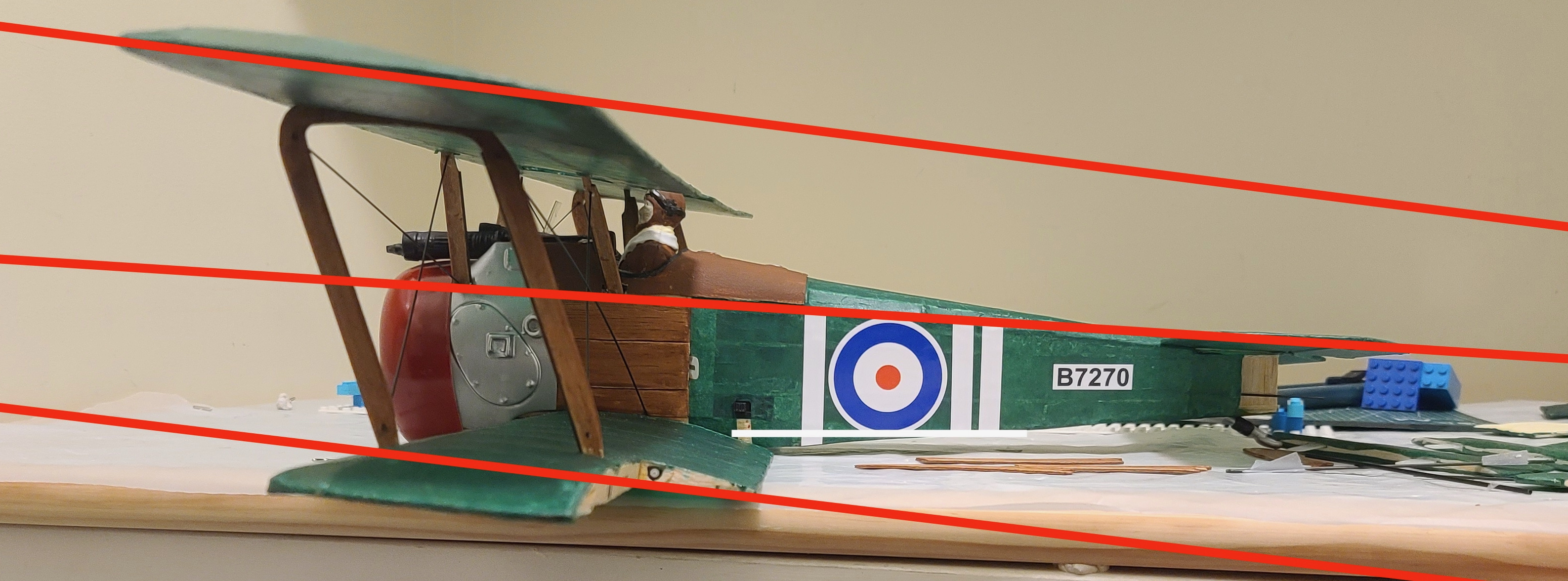
The upper wing and lower wing line up pretty well, and have pretty much the same angle of incidence, which everyone seems to say is important, but the horizontal stabilizer doesn’t. While the main wings have a slight up angle, the horizontal stabilizer does not, which means the angle of incidence is different to the main wings by .. wait for it .. just under 5 degrees. Now some people seem to say 5 degrees is where you should be worried. Well I’m worried, just looking at it doesn’t look right. And this is based on how the plans look. So I’m going to sand down the mounting area for the horizontal stabilizer a bit to bring it down.
In my journey from building balsa free flight models to getting into radio control, the Jumper T-Lite will be the next step. After deciding to get into RC, I bought some second hand planes and two second hand transmitters, a Turnigy TGY 9X and a Spectrum DX4e. These have been great to learn on, but I want something that I’m going to be able to use for all my models and neither of these is going to cut it.
Enter the Jumper T-Lite.
Jumper T-Lite version screen.
As at 25 May 2021, this is a very new machine. There is a lot of excitement about it in the community, and there are a number of videos on YouTube with reviews and analysis of the machine. A lot of this is focused on quad/drone usage, but even the fixed wing fliers like myself come at it from years of experience and skip over some basic steps.
Of course you would expect this basic information to be “in the manual”, but it’s not. The 4 page “quick start” guide that comes with the T-Lite has one single page of actual instructions which pretty much focus on binding with a receiver, but don’t say what do do with the setup after that. Scroll down for some help with this.
The Open-Tx documentation online is about version 2.2 predating even the 2.3 major release that includes the T-Lite. This is open source software of course, so its not really fair to criticize, but it is important to understand what this all means. It mostly means that to get the most out of this very powerful gadget, you need to find bits and pieces of information all over the internet, including on YouTube, forums and blogs (like this one).
So what I’m going to try to do here is distill what I have found helpful into a bit of a real “Quick Start Guide” that hopefully will help you to get started using it. This isn’t intended to be comprehensive documentation, I hope it helps. It’s helping me to write it!
Initial Setup
Most of the unbox videos you see online cover the basics of turning putting on the antenna (VERY important) and putting the correct 18650 lipo battery (flat top not button top) in the right way round (Positive to the right if you have the T-Lite open in front of you – check this very carefully). These batteries are pretty easy to find, I bought mine from Battery World in Vancouver.
Yes – the USB cable does charge the battery! (but it takes a few hours). You can charge batteries in a separate charger, but you don’t need one. The internal charger won’t overcharge the battery so leave it charging till the light goes off.
Turning on the Transmitter
Things like what comes up first, “Throttle warning” (mode 2). etc.
Using the Keys on the T-Lite
One of the nice things about the T-Lite is the “keypad” – the keys on the receiver. They are labeled, but it’s not really intuitive and apparently the labels rub off over time, so I’ll give you this quick reference table that might help.
Key Label
Function
Usage/Comments
ENT
Enter
Select an item for editing, select an item from a list. Confirm action or entry
RTN
Return
Not “return” like on a computer keyboard, this means “return back” to the previous step, or exit out of what you are doing.
UP
Up
This one is pretty straight forward, move up a screen, move up a list, move to the previous item when you are selecting options. Sometimes “up” means “up the alphabet”, which intuitively seems to be going backwards because up from “F” is “E” (previous).
DN
Down
Opposite of UP
SYS
System or Left
Depending on the context, this button can mean “System” or “Left”. For example when you first turn on the radio you will be in a Model. Press SYS to take you to the main SYStem setup menu for the radio. Once you in the setup menu, MDL and SYS will take you forwards in backwards through the setup pages. Sometimes this can be confusing because you might expect “RTN” to be “go back” but sometimes it might be the SYS button you need to “go left”. So the SYS button will sometimes work as “move left” or “page left”.
MDL
Model or Right
When in a particular model, the MDL button will take you to the model selection screen. But if you are navigating on various screens, the MDL button will usually be a “move right” or “page right”.
Selecting a model
When you turn on the T-Lite you will be “in” the model that you were in last time you used it.
This usually makes sense, the transmitter assumes you want to control/fly the last model you were working with, but If you want to change to a different model or create a new model, press the “MDL” button. This takes you to the model selection screen.
If you are on one of the setup pages for a specific model, you need to press “RTN” first to take you back to the main model screen. Then you can press MDL to get to the model selection screen.
Creating a new model and binding to a receiver
The quickest and simplest way to set up a new model to fly is this:
Get to the model selection screen – usually by pressing MDL from the main model screen or system setup
Move to an empty model slot
Press and hold ENT – this pops up a menu. Use UP/DN to select “Add Model”, press ENT
You are now in a new model – you can change the name now, but its not necessary. You can always change it later.
Press MDL to go to the “Model Setup” page.
Press DN to move down to an empty slot.
Press and hold ENT to popup the menu and select “Create Model”, again using ENT.
Follow the prompts through the wizard. What is weird about the Wizard is that on each page, when you are done with the page you actually press RTN to go to the next page.
New Firmware – should you? Yes now 2.3.14 is good
At this point (25 May 2021), I’d say don’t update the firmware. The version that comes out of the box is good and it works. I flashed a new ‘nightly build’ firmware I downloaded using Open-TX companion and all the gimbals and switches stopped working. I had to “Factory Reset” (see below) in order to get it back from the dead.
But now as at 16 Aug 2021 there is a very clean and solid new “Release” firmware build 2.3.14 that works great and has a couple of but fixes you might want. Like one that stops the battery from draining so fast.
For some reason Open-TX won’t update the firmware from my Mac, so I had to follow the instructions for copying the new firmware to my SD card and booting the radio in boot loader mode. This works just fine.
To start the radio in boot loader mode. Press and hold the two middle trim buttons at the bottom (so the right trim for Rudder and the left trim for ailerons) and then press the power button.
Open-TX companion
The standard Open-TX companion (stable release 2.3.12 or earlier) will not work with the T-Lite as at 25 May 2021. Until Open-TX officially declares 2.3.13 or higher as a new stable release version, T-Lite is not available as an option and you won’t be able to use it with your radio. If you do (I tried) you might even brick it. Recovering is doable but not fun, so just don’t try.
Update as at 24 June 2021 2.3.13 has been released and the Jumper T-Lite is now supported by the Open-TX companion.
One thing to watch out for (maybe only on the Mac), when you first plugin the transmitter to the USB port it can take a long time for the “T-LITE” drive to mount and show up as a device on your Mac. Until it does, Companion will not be able to read or write models. It says it can’t find the radio. Just be patient. Sometimes VERY patient, but it will get there eventually.
Factory Reset
If you are hooped – your transmitter is messed up and nothing seems to be working. You get multiple warnings when you boot and you don’t know what is going on, it might be time for a “Factory Reset”. Luckily this is easy – but its tricky to find. This is how you do it:-
Power off and restart your T-Lite
Press SYS to go to the Radio System menu
Press MDL 5 times to get to the Hardware page.
Press DN to go to the Factory Reset option
Press ENT to select Factory Reset – you are not done yet.
Press ENT again to confirm.
You are done.
Don’t touch the Channel Order
The standard out of the box channel order for the Jumper T-Lite is AETR. Don’t change it.
Also set up the Mixes page to match – for every model. Always do this and never change it:
Channel #1 – Ailerons
Channel #2 – Elevator
Channel #3 – Throttle
Channel #4 – Rudder
Always! The only thing you should ever change are the input mixes (e.g. add aileron input into rudder) and rates, and other channels (channel > 4) for flaps, landing gear, 2nd aileron channel – etc.
The multi-protocol module will automatically translate if you use something like a Spectrum/DSMX receiver that expects a different channel order on the receiver. So if you use a DSMX receiver with the channels set as above in the radio, the radio will map the channels when it sends out the signal – so what you will plug in on the plane will be:
Channel 1 – ESC
Channel 2 – Ailerons
Channel 3 – Elevator
Channel 4 – Rudder
And you don’t have to do anything! It just works.
If you feel like you want to change to TAER because you a used to it – don’t!If you change it you will break things. If you change the default channel order in the radio or in Open-TX companion, weird things will happen, like the motor running when you move the aileron stick, or your motor just not working. Both of these things happened to me and it wasn’t fun figuring out what was wrong.
[If you are an advanced user you can change this, but you have to use different firmware on your radio – the firmware must be built for the same channel order you select. If you really know what you are doing, follow the information at multi-module.org carefully.]
In short – the channel order for the Jumper T-Lite is AETR (Ailerons = channel #1, Elevator = channel #2, Throttle = channel #3, Rudder = channel #4) – don’t change it.
I bought 5 second hand RC planes to get me started in Radio Control plane flying. 3 of them had Turnigy equipment with a Turnigy TGY 9X transmitter (with a Turnigy RF 9Xv2 protocol module) already bound.
But then I bought the new Jumper T-Lite transmitter with the JP4IN1 (multi-protocol) module from BangGood and I decided I wanted to stop using the clunky old 9X, and switch those planes over to my wonderful new T-Lite.
I thought – great, it’s “multiprotocol” – this should be easy, but when I tried to set the T-Lite to “Turnigy” – well it wasn’t there! No such option. No “Turnigy” at all not even close. So I got online, went to google, YouTube, RCGroups.com and I could not find anything that would tell me how to bind my T-Lite to the Turnigy 9X8Cv2 receivers that I got with those 3 second-hand planes.
I looked for binding the Jumper T16 – still no luck. Of course there was lots about binding the T16 in general, and lots of great info about binding the T-Lite to all kinds of receivers, but nothing about binding them with Turnigy receivers.
I did figure out that the Turnigy probably used AFHDS or AFHDS2a and I found this website that has a comprehensive list of all the possible protocols, but I still couldn’t figure out which protocol to choose. It was tantilisingly close, and I tried the two FlySky protocols that listed “AFHDS” but … no joy, and the light kept blinking and the receiver kept beeping.
Then I found a wonderful article on the FliteTest forum that gave me the final clue. It was just by pure chance, or persistent searching, because this article doesn’t say anything about Open-Tx or binding or any of those things, but a user called lrussi750 says one very important thing.
The (FlySky) TH9X and the (Turnigy) 9X are the same radio and the only difference I’ve seen is color. I have both radios.
Eureka! So – this should mean that if I select “FlySky” on my T-Lite it should be able to bind. Well I tried it and it works! This is a screenshot of the protocol setting I used to bind the Turnigy 9X8Cv2 receiver to my Jumper T-Lite.
Use FlySky – subtype (subprotocol) Std – and it will work!
I do feel kind of silly that I didn’t get it when I figured out that Turnigy uses AFHDS, but I am just so happy!
And – very happy with the Jumper T-Lite – what a great little radio.
But there are some details that make more sense to post as text, so I’m including them here.
Build Order
As I worked through building the model, I realized that the numbered instructions should NOT be followed “step by step”. It’s not a big problem, just follow these steps and you will find that the model comes together much easier.
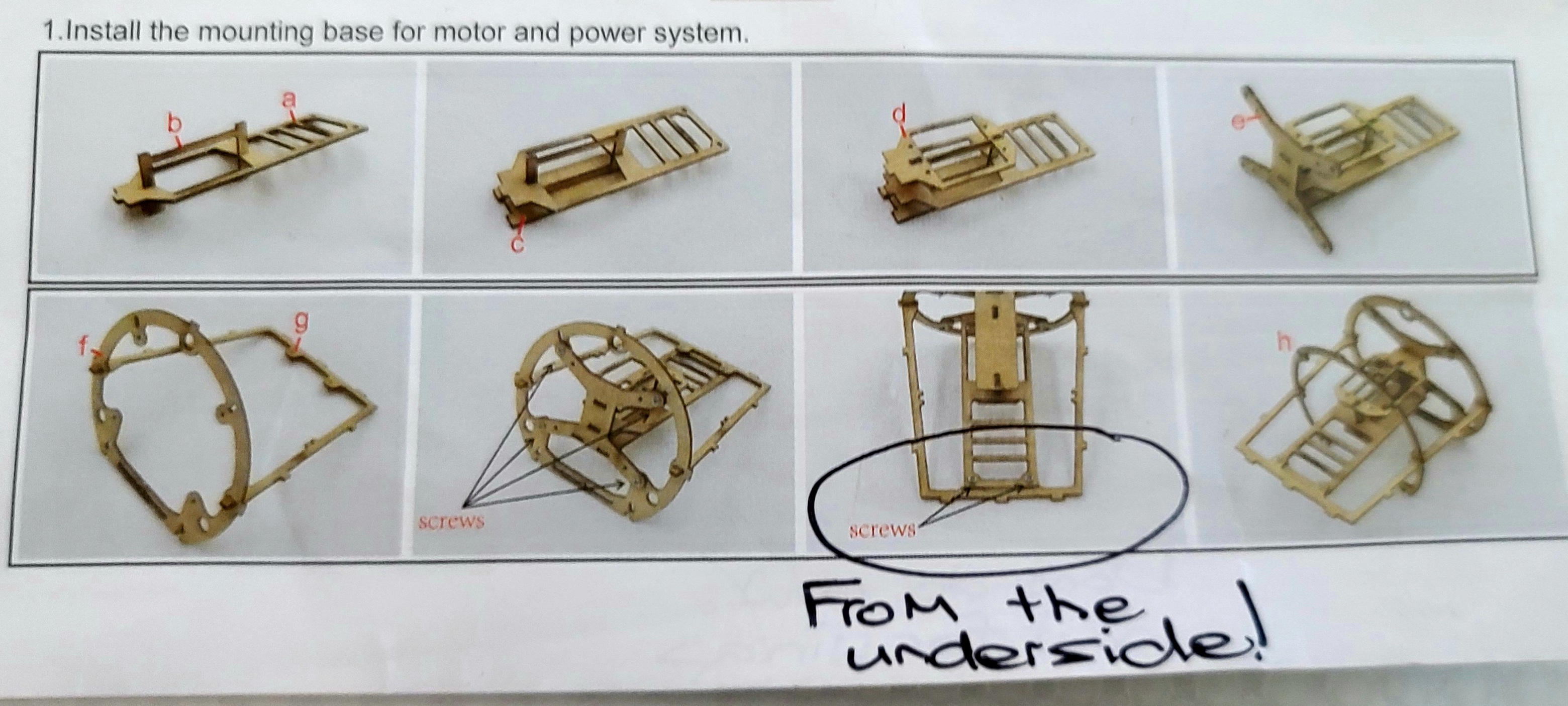
Install the mounting base for the motor and power system as per the plan at 1.
Install the electronics in the mounting base. The Instructions have this at step 6. Do the first few items from Step 6, but do not connect the servos to the pushrods yet, and don’t connect the elevator and rudder at the end of Step 6. Test the electronics with a transmitter – make sure the servos and motor are working.
Assemble the fuselage – but don’t put on the bottom yet. First insert the pushrods for elevator and rudder and connect them to the servos as per the pictures in Step 6. These can be connected to the elevator and rudder later, but it’s much better to connect to the servos now. Put on the bottom of the fuselage _after_ testing again that the electronics are working and the pushrods move back and forth, even though they are not connected to the rudder and elevator yet.
Don’t install the magnets in the fuselage in Step 2, so don’t following the printed instructions for this. Wait till you have the cowling finished.
Build the cowling, then line up the magnets in the fuselage with the cowling. Make sure to get the polarity of the magnets right so they click into place instead of pushing apart. This is covered in detail on YouTube here: https://youtu.be/RJmyAGB5h34
Build the wheels, but don’t put the undercarriage on the fuselage yet, wait till you have put on the wings first.
Assemble the wings. Instructions Step 5. If you are going to paint. Assemble but don’t install on the fuselage!
Optional step – if you want to paint, do it now before you put everything together.
Install the wings on the plane (this is the second part of Instructions Step 5).
Assemble the elevator and rudder and install on the plane, connect the control horns to the control rods as per the picture at the very end of Instructions Step 6. Test it again, make sure everything is working smoothly.
Install the undercarriage and wheels and put on the propeller.
Congratulations! Gong xi! You are done!
Corrections/Suggestions
There are some things in the instructions that are not clear, missing or in a couple of places, just plain wrong. These are some key things you need to know.
Screws on the power frame go on the bottom.
If you need to remove the mounting base later for whatever reason (perhaps something isn’t working or you want to change the hole position you are using on the servo arms), then if the screws are put in from the top you will have to cut a hole in the top of the fuselage to remove the screws and slide out the mounting base. I did this, it wasn’t pretty.
If you put the screws in from the underside, they are easily accessible via the hatch on the bottom of the fuselage.
This one picture is with the mounting base upside down. All the others are from the top. You might not notice it, but it is very important.
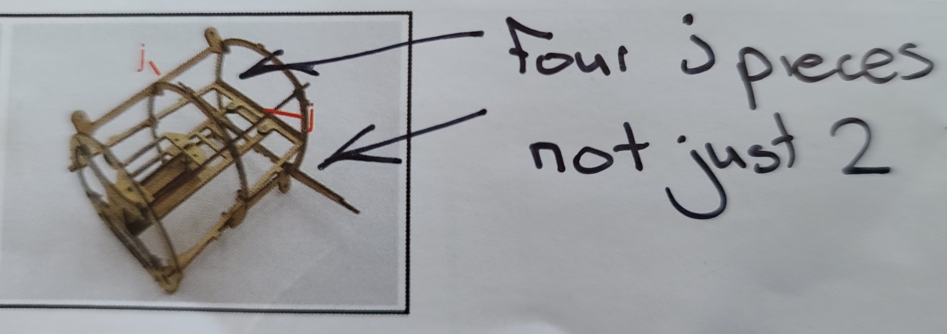
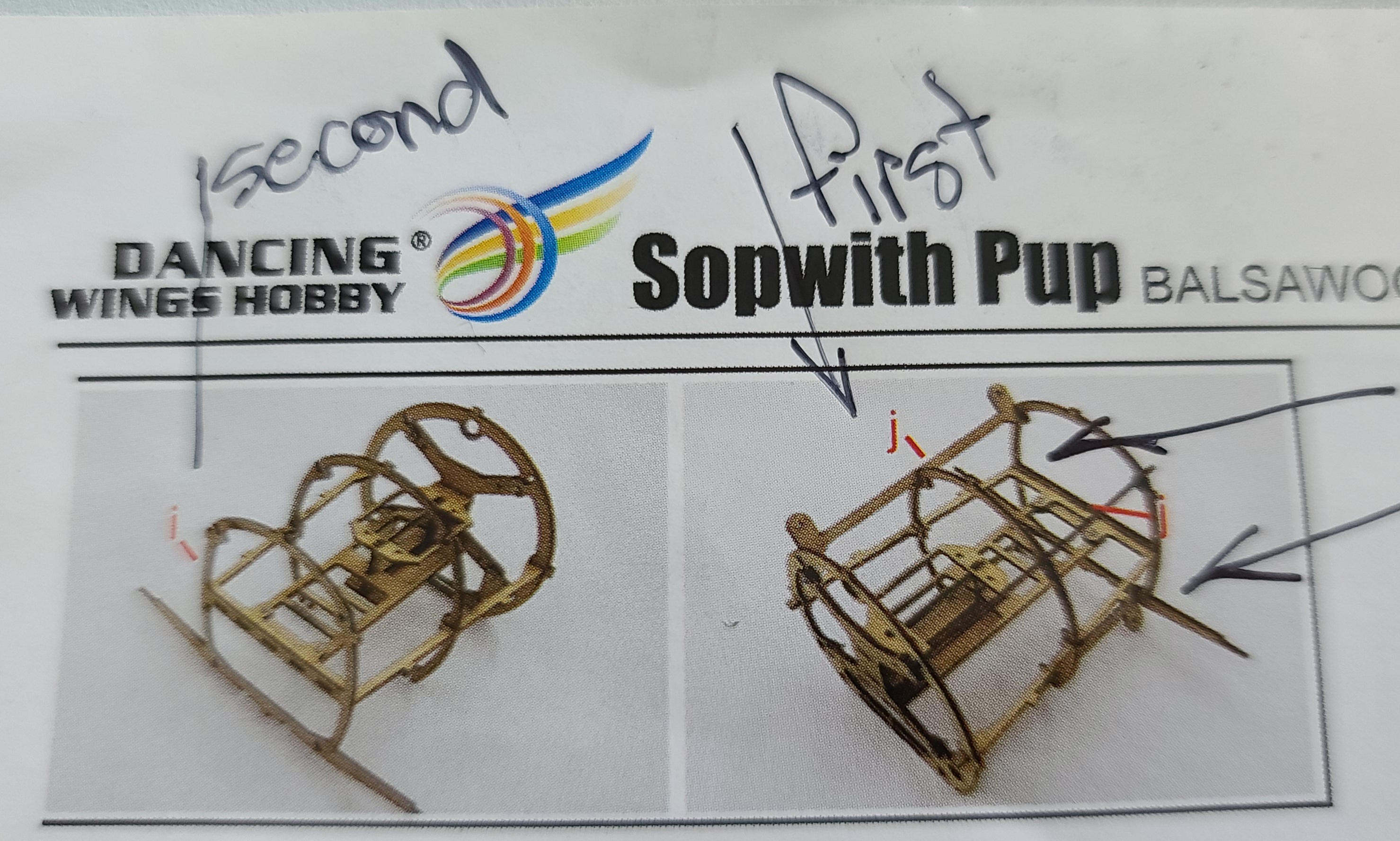
There are four “j” pieces to install on the power system mounting base.
The Instructions only show 2 – actually the picture shows all 4 pieces, but only has 2 red arrows showing 2 “j” pieces to be installed. Find all 4 of these and install them now. It will be very difficult to fix this later if you miss it now.
These two “j” pieces at the bottom are where the undercarriage screws onto the fuselage. If you miss these now you will not be able to install the undercarriage unless you cut open the fuselage and put the “j” pieces in.
Also – install the “j” pieces before you install “I”, so reverse these pictures.
Don’t put the tail peg in right away.
This is more of a suggestion, but I found it so easy to accidentally break the tail peg when doing other parts of the plane. Perhaps delay installing it until just before you put on the elevator and rudder. Also – soak the tail peg in CA glue/super glue for strength. It is very fragile and needs beefing up.
Watch out for the Q ribs
When building the wings there are whole lot of “R” ribs, but only 2 “Q” ribs which go on the very inside of the lower wing. Pay attention to this and don’t accidentally put the Q ribs somewhere else.
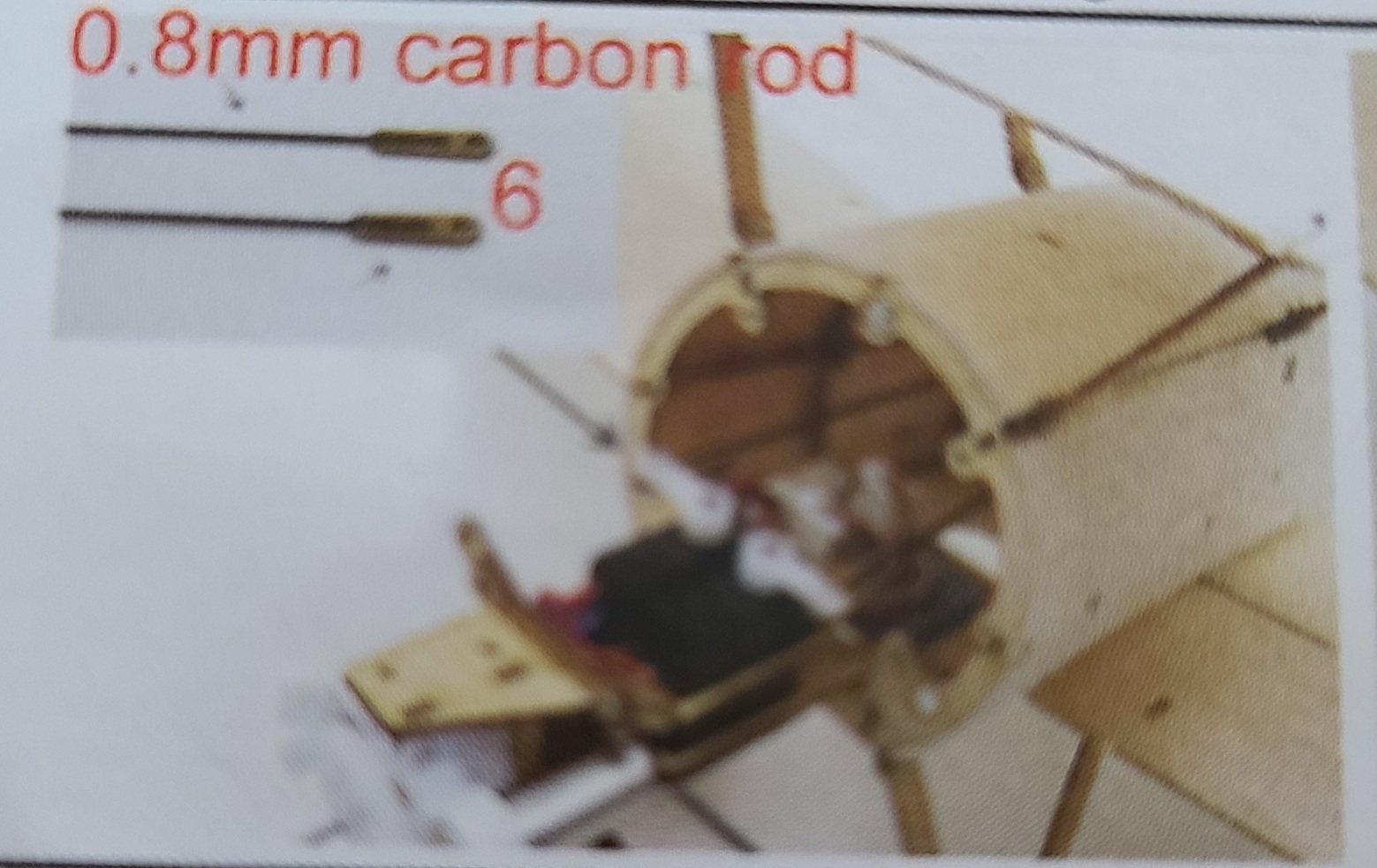
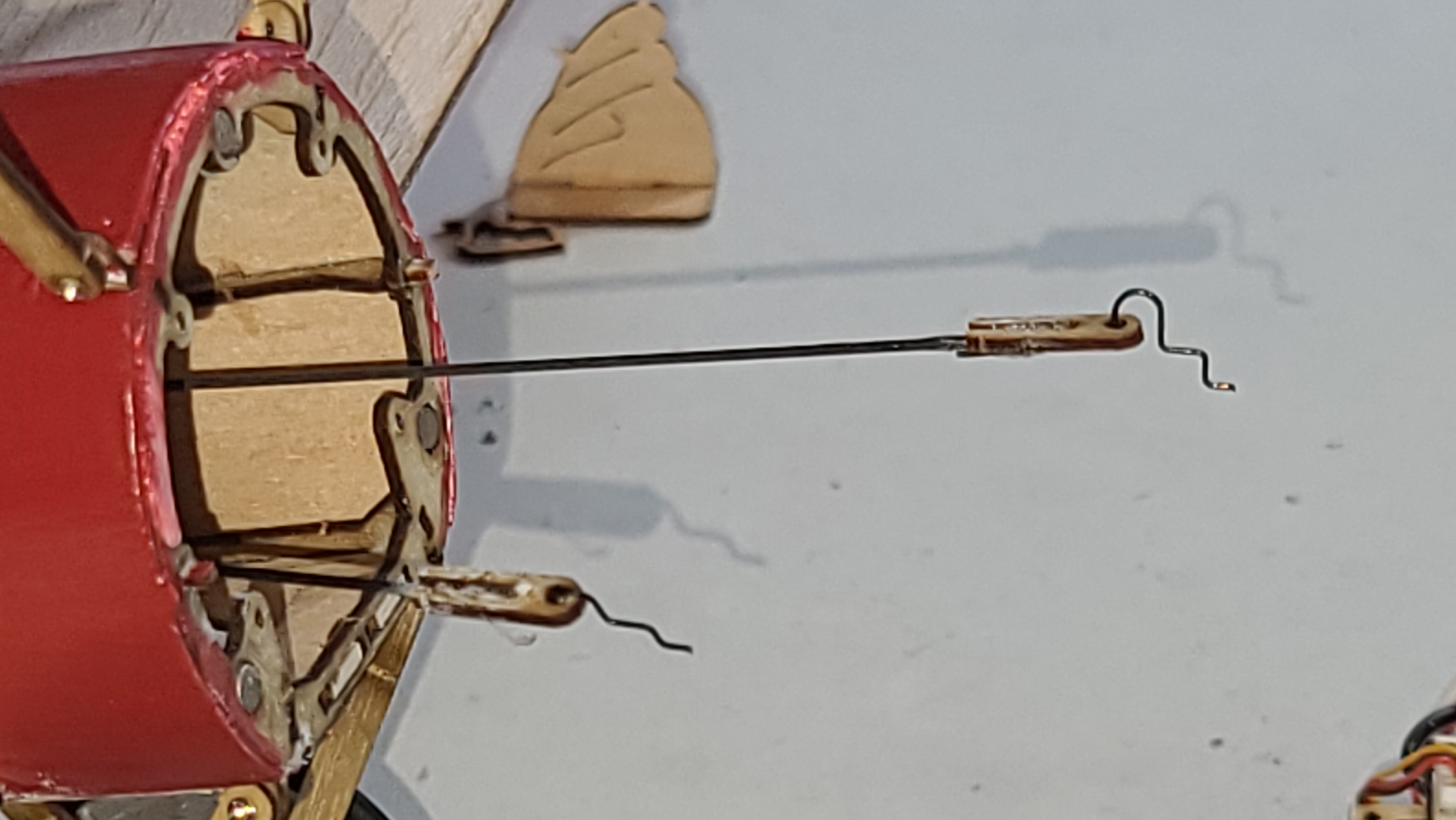
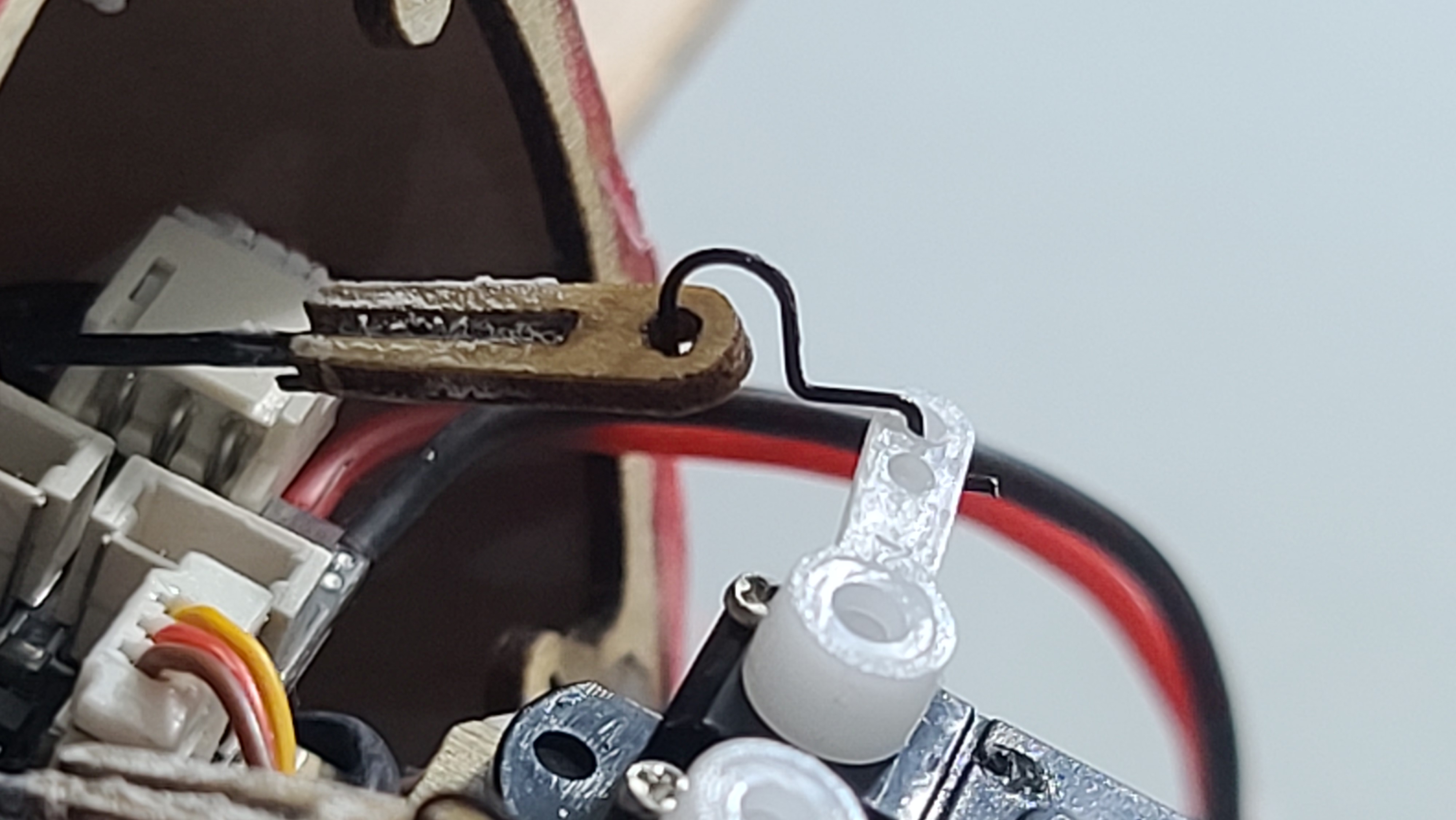
How to connect the pushrods to the servos
The Instructions at Step 6, picture 5 shows how to connect the “6” wooden pieces to the end of the pushrods and then attaching them to the servo arms. But the picture is all you get and it’s really not clear how to connect the wire pieces provided to the servo arms. Zooming in the picture on the instructions doesn’t make it clear, because the picture is so grainy.
So I made my best guess and here are pictures showing how I did it. Take note of the two pictures showing the pushrod connection to the servos. One works and one doesn’t. I tried the first and it seemed fine, but the plane flew around in a circle because the pushrods were catching on the inside of the fuselage. Do it the second way, this brings the rods down lower and away from the fuselage.
It works! (Maybe there is a better way, but this way works).
The picture from the Instructions is not very clear.I glued the small wire pieces to the wooden “6” pieces on the end of the control rods.Don’t do this. If you do this, the rods might rub or stick against the fuselage.Do this instead – not a huge difference, but might affect how the plane flies
Glue the wheels (carefully!)
You don’t want the wheels to stick, they work and I got some really nice takeoffs from the kit wheels. I guess it should have been obvious, but the wheels need to be glued to the nylon bushes and the o-ring “tires” need to be glued to the wooden rims. If you don’t you run the risk of them popping off on the field. I used “super glue” (CA glue) because it is plastic to wood and rubber to wood. Be very careful not to get any glue inside the bush so that the wheel can spin nicely on the axle.
Reinforce the undercarriage
I flew my plane on a wonderful field with some very thick grass which cushioned my many crashes while I was tuning it. What did happen a number of times when crashing or even having a good landing, was the undercarriage would break off when it hit the grass. So I reinforced it with 4 pieces of carbon fiber rod. This also helped with the centre of gravity because the undercarriage is mostly forward of the CoG.
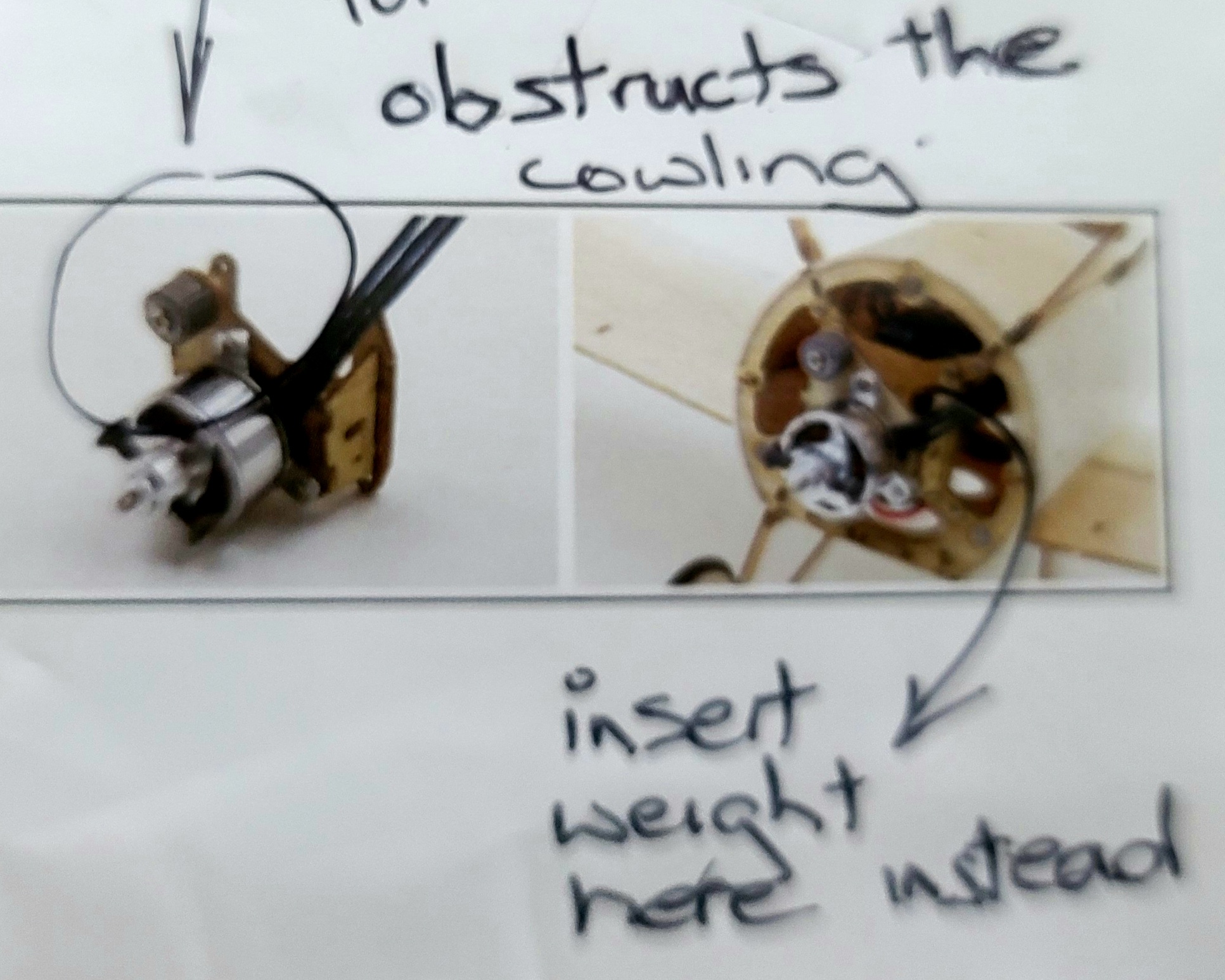
If using a brushless motor don’t install the lead weights as per the Instructions.
If you put the lead weight at the top of the special mounting base shown in “8. Assemble the Brushless Motor”, you will not be able to put the cowling on. Following the build instructions for “brushless motor”, the weight wrapped around the screw gets in the way, preventing the cowling from being clicked onto it’s magnet.
Instead, I suggest you install any weight required in the bays behind the motor, there is one at the top and one at the bottom.
You will need a lot of weight. The included weight was not enough to get the centre of gravity right for me. I had to add more, for a total of 12g, to get it the centre of gravity to where it should be according to the instructions.
This is for brushless motor only. I don’t know what happens with a brushed motor.
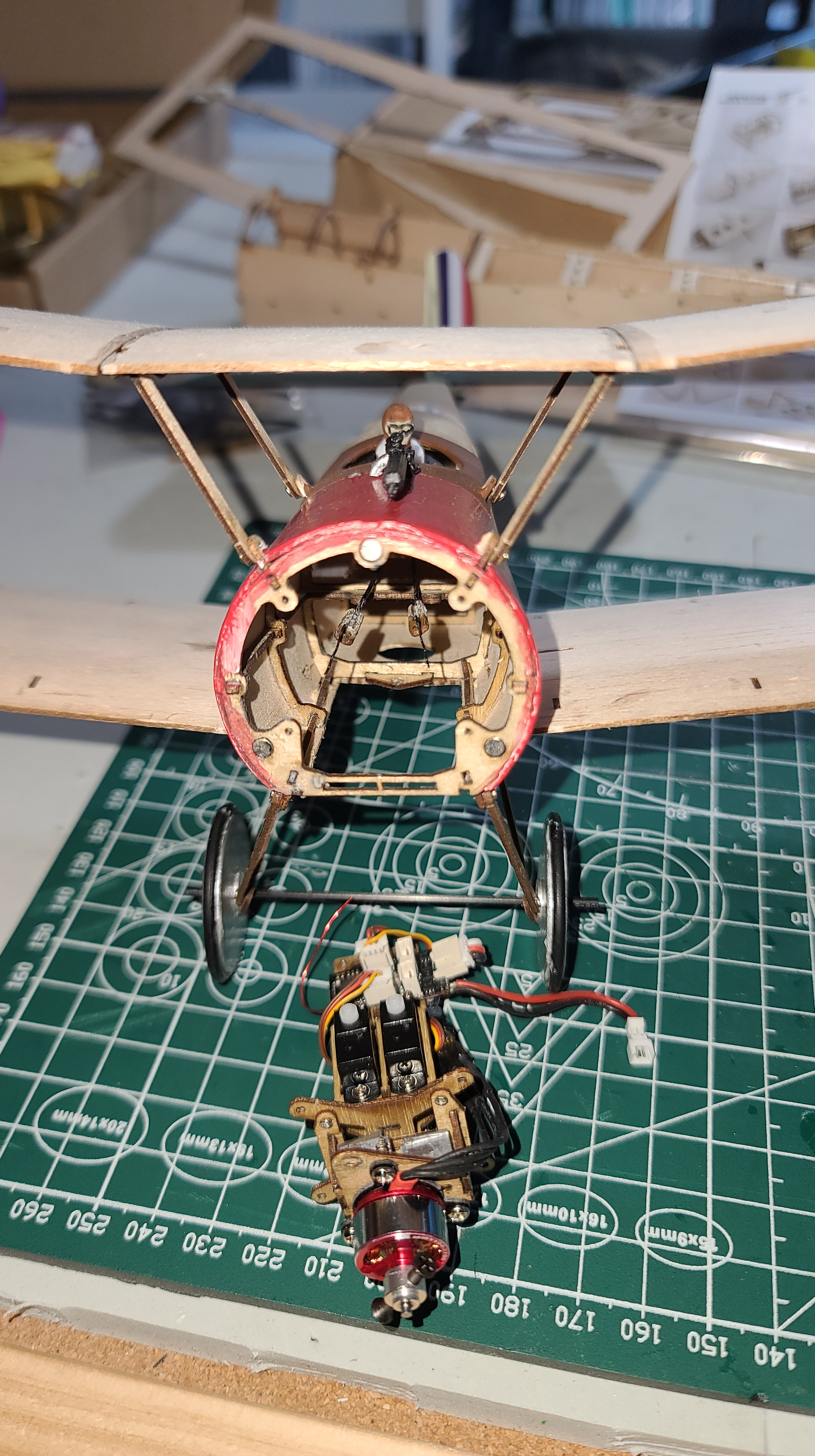
I actually needed a lot of weight to bring the centre of gravity forward in order for the plane to fly. I didn’t keep track of it all, but here are some pictures. The weight that came with the kit + two pieces of solder + some ‘white tack’ plastic putty packed into the cowling. I’m sure it’s more than 10g all up.
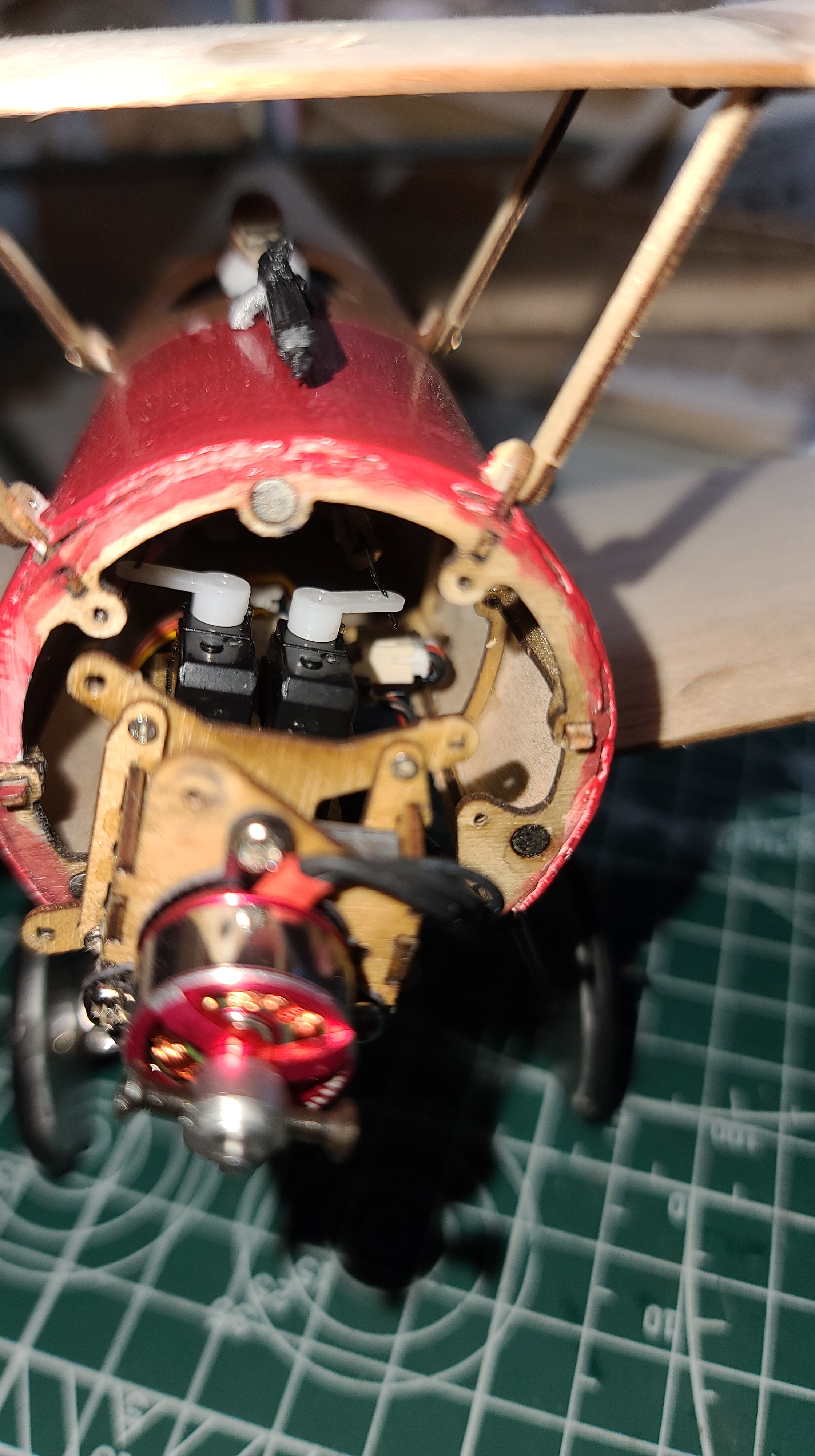
Installing the recommended brushless MM1104 motor is tricky
There are combo packs online (e.g. Amazon where I bought mine) that include the recommended MM1104 motor from AEORC. When you try to screw the motor onto the provided special mounting base, it will not fit cleanly. I had to drill new holes because the provided ones didn’t line up with the holes on the triangular engine mount. Even then, one of the screws barely has any purchase on the mounting plate. It does work though, although it doesn’t look tidy, and the plane will fly with this motor mounted to the mounting base. Here are a couple of pictures that show how it looks:
Brushless MM1104 motor mounted on the mounting base.The screw on the bottom left barely has any purchase on the mounting base.
Receiver: AEORC Rx144-E DSMX compatible mini micro receiver with built in 5A/1S ESC. Note the “E” – this is the one with the built in brushless ESC, without the E, you will need an external ESC.
I found transmitter setup was critical to getting the Sopwith Pup to fly well. The elevator is very twitchy, so I reduced the rate (weight) on the elevator to 66% and with a 35% exponential (expo). The rudder on the other hand needs all the throw it can get, so I have the weight at 100%, but the expo at 30% which worked quite well.
Final Comments
The model as built following these instructions, with painting, looks great! I am very happy with the look, everything is working and with some tuning after the maiden flight and some additional test flights.
But it’s very heavy. 65.5g total weight. The specifications for the plane say flying weight is 42-50 grams, so it is 15.5 grams overweight.
If I weight the model with the painting that I did, it comes out to 70g. I built the same model again without painting – 65g, but I don’t think I could get it any lighter.
I don’t want to break my lovely plane, so I have ordered a new kit, and I’ve built it again, bare bones, following my instructions above. So the extra weight isn’t a problem, it really does “fly like a bird”.
[And I’ve updated this blog based on the second build, so the hints and suggestions you see are what you need to build your own].
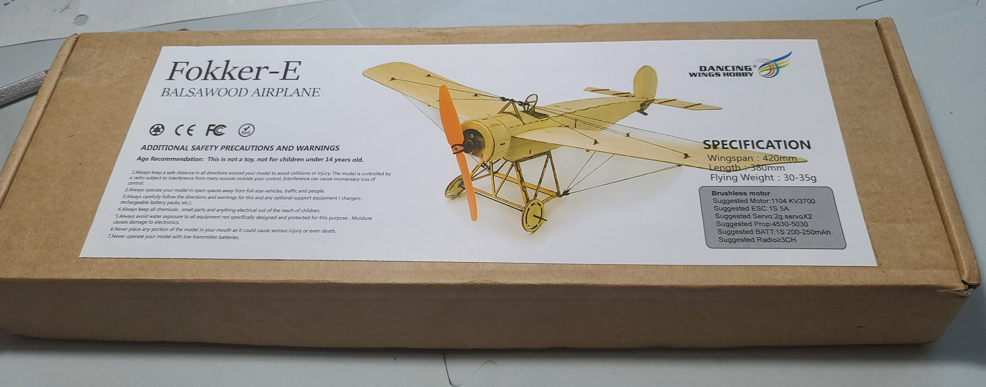
When I built the Dancing Wings Hobby Fokker-E (the small 420 mm wingspan version), I learned a lot of very interesting things. Well, I find them interesting. So I thought I would share them in case anyone else finds them interesting or even helpful.
Instructions
The instructions are cryptic. A single page with lots of colour pictures and some limited and very tiny writing. I needed a magnifying glass to make sure I didn’t miss important details. There are lots of comments about the instructions from buyers, so I think others have the same problem I did.
You have to read and follow the instructions very, very carefully. I missed one piece, which I didn’t find before it was too late, simply by failing to notice the tiny label on a one of the picture steps.
The instructions also don’t include what you might think is very basic information. Glue is a good example. They don’t say anything about glue. I mostly used standard white wood glue, but sometimes Superglue (CA some people call it). For example I glued in the magnets using Superglue. I guess I made reasonable assumptions, and I think I got it right, but nothing – absolutely nothing in the instructions about what glue to use and where it should be used.
Electronics
There is very little information in the instructions about electronics. The kit I ordered included a brushless motor, but the instructions which described how to install it described a different one, so I had to “figure it out”. There was nothing about how to install an ESC, receiver or servos.
The instructions do say which electronics to buy – but nothing about how to install them.
Youtube Video
There is a Youtube Video! This was a great find, and very, very helpful. There is an animated video from Dancing Wings Hobby, that kind of shows how to put the kit together. Again it doesn’t mention basics like glue, but it does show the order very well, and even gave some additional hints about installing the electronics that you don’t get in the printed instructions. I built the plane with the video open on my laptop and paused in my browser. At each next step, I would hit play, wait a couple of seconds and pause again so I could see the next step. You can find the video here:
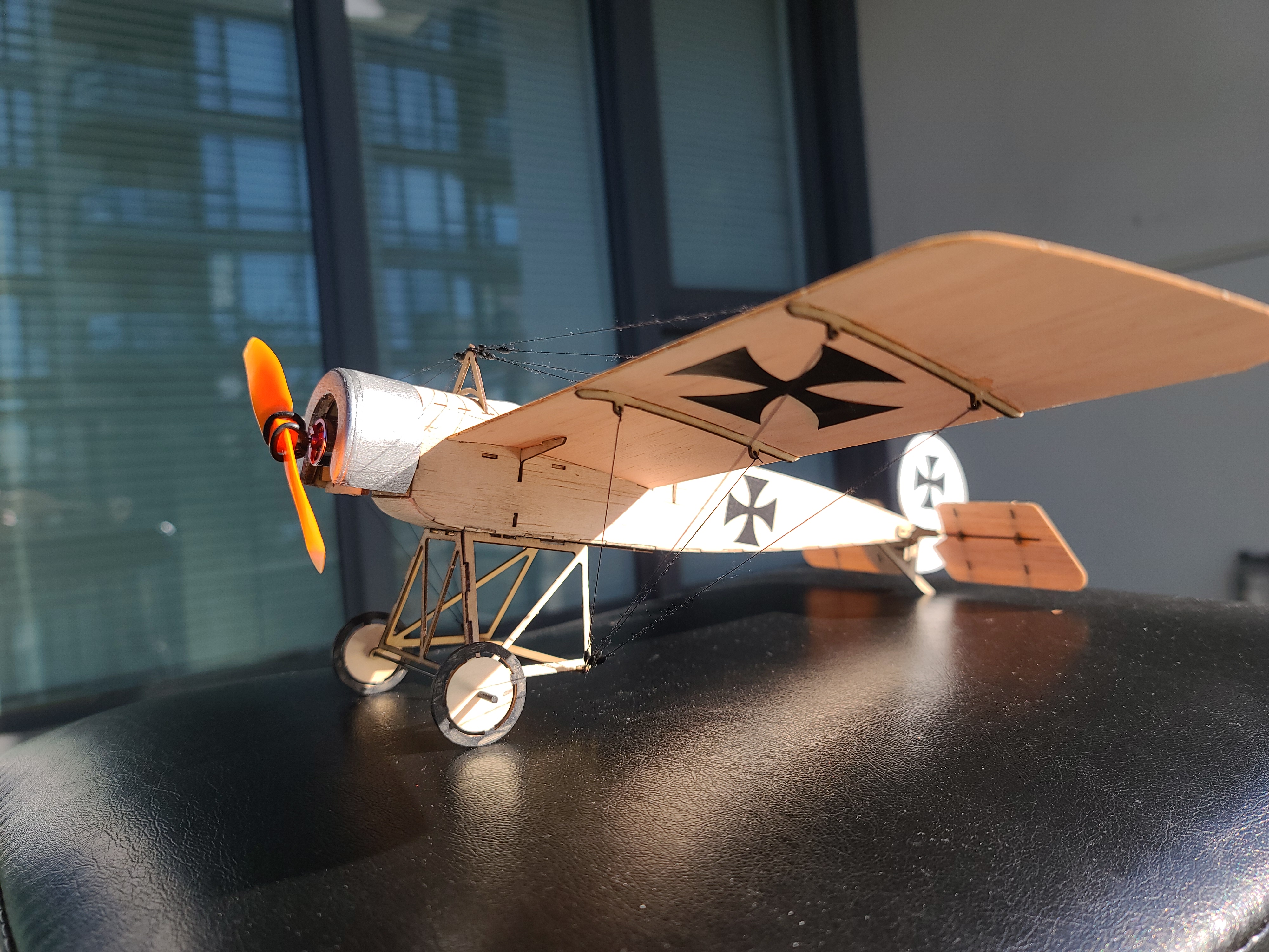
The instructions say nothing about paint or other decorations. The video does show some things like Iron Cross decals and a white rudder that are not in the instructions. They look great. So I painted the rudder white and made some iron cost decals by cutting out some Cricut black vinyl. I’m not sure if that’s what I was supposed to do (there are no decals in the kit), but I think it looks great.
After finishing and trying to paint the wheels, I realized that I should have painted them before putting them on. With all of the very fine detail, such as the rigging and struts, it’s almost impossible to paint after everything is connected, so ask yourself at each step – will I want to paint this? If so – paint it now before installing it. Some things I wish I had painted first:
The wheels
The landing gear
The rudder
The frame in front of the cockpit that holds up the rigging
White stripes on the wings to frame the Iron crosses (see some original pictures)
The pilot
The railing around the cockpit
Magnets
There are several small magnets included and the instructions are very precise about where they need to be placed, but gives no hint about polarity. For example it says to put two magnets on the underside of the cowling. This is to hold the cowling in place. Then somewhere else in the build it says put two magnets on the brackets at the front of the frame that hold the cowling. If you don’t think ahead, you could install these two magnets so that when you try to put the cowling on it will bounce right out, rather than clicking into place. You need to get the polarity right for each and every one.
The thing is – the different pictures and sequences don’t really join this together, so unless you hunt down the “other end” of the magnet you are installing, you won’t know which end is which. So here is what I do:-
Take the magnets apart in pairs.
Mark each magnet with a ‘dot’ using a sharpie to show sides that need to be apart
Find both sides of the magnet connection on the plans.
Make sure to install each magnet with the dot (from step 2) away from the other magnet.
The magnets are also a bit small. I guess this is my opinion, but there are two hints that I am right. The first is that the holes in the balsa for the magnets are far too big for the magnets provided. Around half the size. So even with copious Superglue, the magnet sort of floats in the hole for it. The second hint is that when clicking things like the electronics hatch on the underside of the plane in place, the hatch seems very loose. It feels like it might drop out, the magnet isn’t holding it very tightly. I bought some larger magnets and replaced some of those that came with the kit and got a much more satisfying “click” and much more satisfying and firmer hold.
Continued …
I’m still building this model, so likely there is more to come. This is where I’m at so far:
Dancing Wings Fokker E.III as at 19 April 2021
Maiden Flight and Lessons Learned
Well it’s 7th July 2021 and this plane has flown! You can see the video on YouTube.
The carbon fiber rod in the kit that is for the elevator is very important. This should be the thicker 1.5mm rod and I used the thiner one. I had to fix that.
The rudder was very twitchy. I think this is because the rudder was not stable and was kind of flapping around a bit. The “paper” hinge for the rudder specified in the instructions needs to be fairly strong paper or thin plastic. I replaced the paper I had used with hinges left over from the Sopwith Pup. They are perfect – it would be great if they get included with the kit.
Center of Gravity is very important, I had to include a lot of weight inside the cowling in addition to the lead that came with the kit. Don’t worry, getting the CG right is more important than the total weight. My model is 68g and it flies just fine.
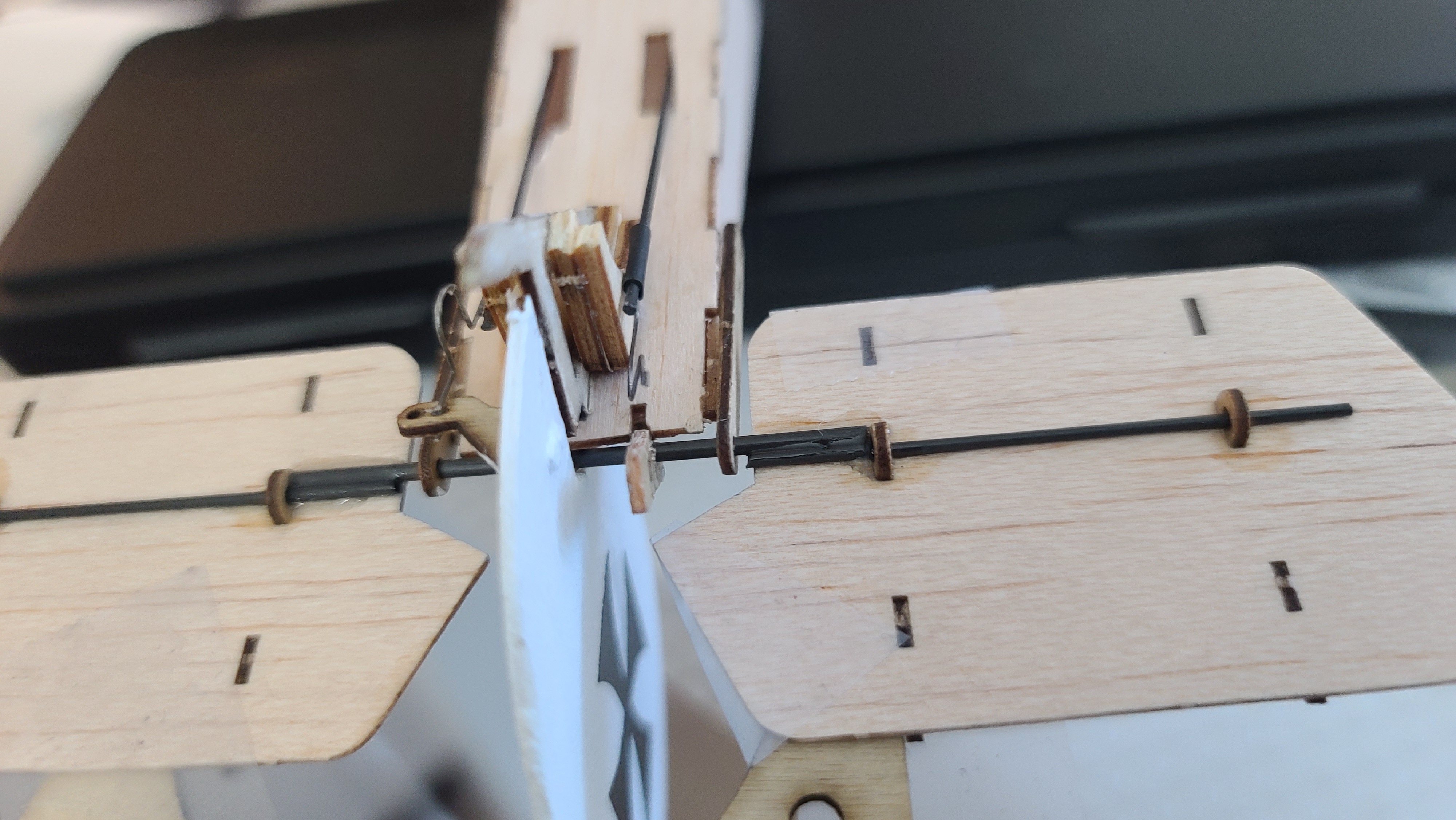
The plane tends to fly up and to the left. There is no down thrust or right thrust on the motor mount in this model, whereas the Sopwith Pup motor mount has a definite down/right angle to the mount. I added some packing on the motor mount to try to point the motor down and to the right.
I never expected the Spanish Inquisition! 😀
Packing under the engine mount to add down thrust and right thrust.New axle for the elevator and hinges for the rudder.
19 years ago I became a Canadian citizen. I was sworn in by a Sikh Canadian wearing a turban. It was one of the proudest moments in my life. Canada isn’t perfect, but I have never once heard a Sikh called a “rag head” – which I was shocked to hear when I was last in Australia, only 2 years ago.
Racism in Australia is nasty. It’s everywhere. Implicitly and explicitly. If you are white in Australia you experience white privilege every day, whether you know it or not.
Racism in Australia is deep, widespread and affects everyone who is not white anglosaxon. Yes seriously, “Real Australians” are better than anyone who:-
Speaks with any kind of non-English accent
Uses a non-English language ‘in public’ – even a native Australian language for god sake.
Is not from a “white” country (Australia, South Africa, UK, Canada, USA)
is from non-English speaking European countries.
Has non-white skin or features.
Doesn’t follow a Christian religion
Has special needs like autism, downs syndrome or cerebral palsy
Came to Australia escaping fascism, war or persecution etc.
if they were forced to escape on a boat thats even worse.
Even if they’ve lived in Australia for 60,000 years – not good enough, and actually – thats the worst.
As an immigrant in Canada I had it easy. I came from a “white” country – Australia. I saw what happened to other immigrants to Canada with more experience and qualifications than me but not lucky enough to be white. I experienced white privilege and I know how lucky I am. But no matter how bad it is in Canada – Australia is worse.
Australian racism is tiered. It is worse for some than for others. If you are from Europe but have white skin, you are almost ok, especially if you learn to drop your accent. Darker skinned Europeans are worse but still not too bad. Asians are probably next- and black skinned people are probably almost ok if they come from the USA, but less ok if they are from Africa or PNG or New Zealand.
But everyone in Australia knows – the Aboriginal people of Australia are at the bottom. Those who came first, who lived in Australia for 60,000 years before the whites arrived, who have their own “Australian” languages and culture, and who had their lives and land taken so that “real Australians” could have a place to live, they are looked down on by everyone else.
All Australians know; white, European, Asian, African, Middle Eastern – they all know they have someone else to put down. Australian indigenous people are at the bottom of the pile. They are abused, tortured and killed by police with impunity. They are treated with disdain, ignored, insulted, manipulated and used. They are ridiculed in public but more in private by people who should know better.
It’s Australia’s shame. I’m ashamed of it. It’s really way past time to start doing something about all tiers of racism in Australia, but especially when it comes to first Australians.
Why not start with the most meaningful thing that needs to be fixed? Make the change first that will matter the most.
Update: The city has fixed this! WOW! Sometime in early 2012 it changed (I was away so I don’t know when), I have to give kudos for fixing the problem, but the messages still has to be – think about this in the first place, please!
If you drive north or south on 101 Street through the 111 Avenue intersection you will know what I mean.
Not that I’m saying it’s happening, but is it possible that someone might design an intersection like this to cause fender bender’s? Hypothetically it might be someone who knew someone who worked for an insurance company! Not that I’m saying that’s what’s happening of course, but just trying to figure out any kind of logical explanation for the design (I’ll try to describe it below), it just seems like it’s only purpose is to cause accidents, but not serious ones. I’m just saying …
So imagine if you will, driving in the left lane down the road. The right lane as usual has cars parked, so you usually can’t drive there except during peak hour, normal Edmonton stuff. You approach 111th avenue going South. You’re going downtown. As you approach, slow down, light is red. Ooops – whats going on … this lane doesn’t go ‘straight through’ suddenly you realize that this lane has become a left turn lane. What? Damn! Ok – and a bunch of other people have the same problem – ok now everyone is trying to merge – lotsa unexpected merging. How many fender benders here? Insurance companies- kaching!!! But wait – thats not all!
Ok – you’re merged over, whew! Ok, light changes, into the next lane going south. WHOA what the? After you get through the intersection the lane does this weird wiggle back left to where it was, as if the ‘straight through’ you thought you were on kept going straight through. If you don’t wiggle you hit the guy in the right lane. Bang!, another fender bender, because of the cars parked along the right hand side even during peak hour. Wow – way to cause damage guys. So – what is that for City Transportation Department? Saved some money? Can’t figure that? Traffic Flow? Dunno? Might have something to do with the buses? Definitely not safety for sure!
I just think the cost of insurance and accidents should be included when ‘costings’ of road decisions go to council!