I ordered the “micro” scale model of the Sopwith Pub by Dancing Wings Hobby from Amazon as a kit in including an electric motor, ESC (Electronic Speed Controller) and 2 servos. All I need to buy (I thought) was a receiver and I’d have everything I needed to build my first complete radio controlled model from scratch.
And so the journey began.
A lot of the details you can see on my YouTube channel “Tim the Plane Man”. The playlist is here: https://www.youtube.com/playlist?list=PL9Qx6K4kAW68N7ubtBHgx95-xxovnWLq-
But there are some details that make more sense to post as text, so I’m including them here.
Build Order
As I worked through building the model, I realized that the numbered instructions should NOT be followed “step by step”. It’s not a big problem, just follow these steps and you will find that the model comes together much easier.
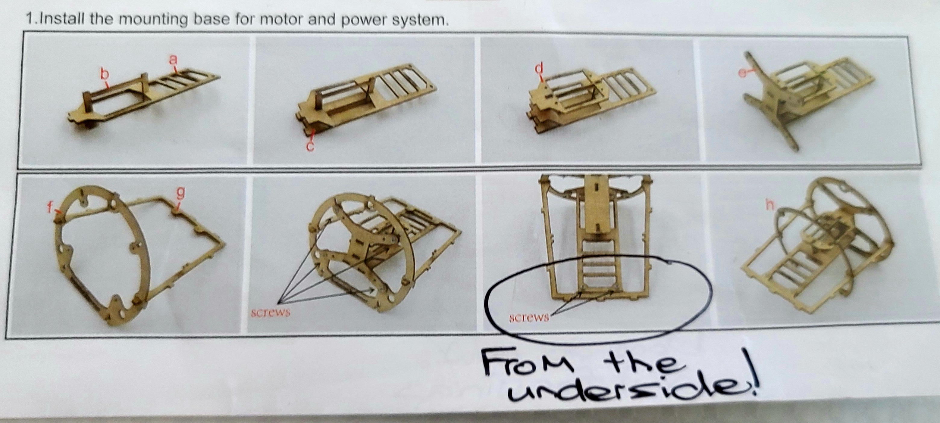
- Install the mounting base for the motor and power system as per the plan at 1.
- Install the electronics in the mounting base. The Instructions have this at step 6. Do the first few items from Step 6, but do not connect the servos to the pushrods yet, and don’t connect the elevator and rudder at the end of Step 6. Test the electronics with a transmitter – make sure the servos and motor are working.
- Assemble the fuselage – but don’t put on the bottom yet. First insert the pushrods for elevator and rudder and connect them to the servos as per the pictures in Step 6. These can be connected to the elevator and rudder later, but it’s much better to connect to the servos now. Put on the bottom of the fuselage _after_ testing again that the electronics are working and the pushrods move back and forth, even though they are not connected to the rudder and elevator yet.
- Don’t install the magnets in the fuselage in Step 2, so don’t following the printed instructions for this. Wait till you have the cowling finished.
- Build the cowling, then line up the magnets in the fuselage with the cowling. Make sure to get the polarity of the magnets right so they click into place instead of pushing apart. This is covered in detail on YouTube here: https://youtu.be/RJmyAGB5h34
- Build the wheels, but don’t put the undercarriage on the fuselage yet, wait till you have put on the wings first.
- Assemble the wings. Instructions Step 5. If you are going to paint. Assemble but don’t install on the fuselage!
- Optional step – if you want to paint, do it now before you put everything together.
- Install the wings on the plane (this is the second part of Instructions Step 5).
- Assemble the elevator and rudder and install on the plane, connect the control horns to the control rods as per the picture at the very end of Instructions Step 6. Test it again, make sure everything is working smoothly.
- Install the undercarriage and wheels and put on the propeller.
- Congratulations! Gong xi! You are done!

Corrections/Suggestions
There are some things in the instructions that are not clear, missing or in a couple of places, just plain wrong. These are some key things you need to know.
Screws on the power frame go on the bottom.
If you need to remove the mounting base later for whatever reason (perhaps something isn’t working or you want to change the hole position you are using on the servo arms), then if the screws are put in from the top you will have to cut a hole in the top of the fuselage to remove the screws and slide out the mounting base. I did this, it wasn’t pretty.
If you put the screws in from the underside, they are easily accessible via the hatch on the bottom of the fuselage.
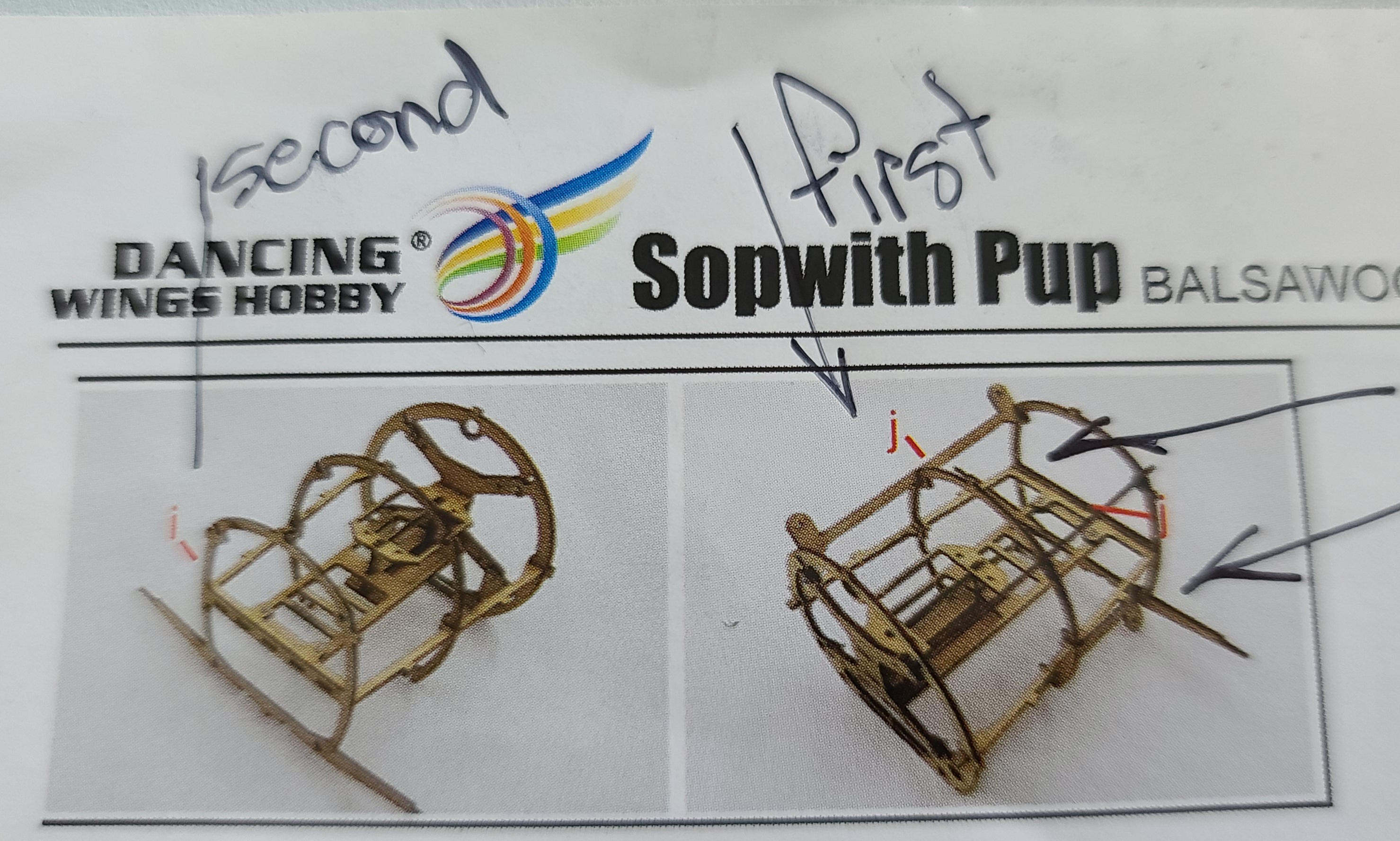
There are four “j” pieces to install on the power system mounting base.
The Instructions only show 2 – actually the picture shows all 4 pieces, but only has 2 red arrows showing 2 “j” pieces to be installed. Find all 4 of these and install them now. It will be very difficult to fix this later if you miss it now.
These two “j” pieces at the bottom are where the undercarriage screws onto the fuselage. If you miss these now you will not be able to install the undercarriage unless you cut open the fuselage and put the “j” pieces in.
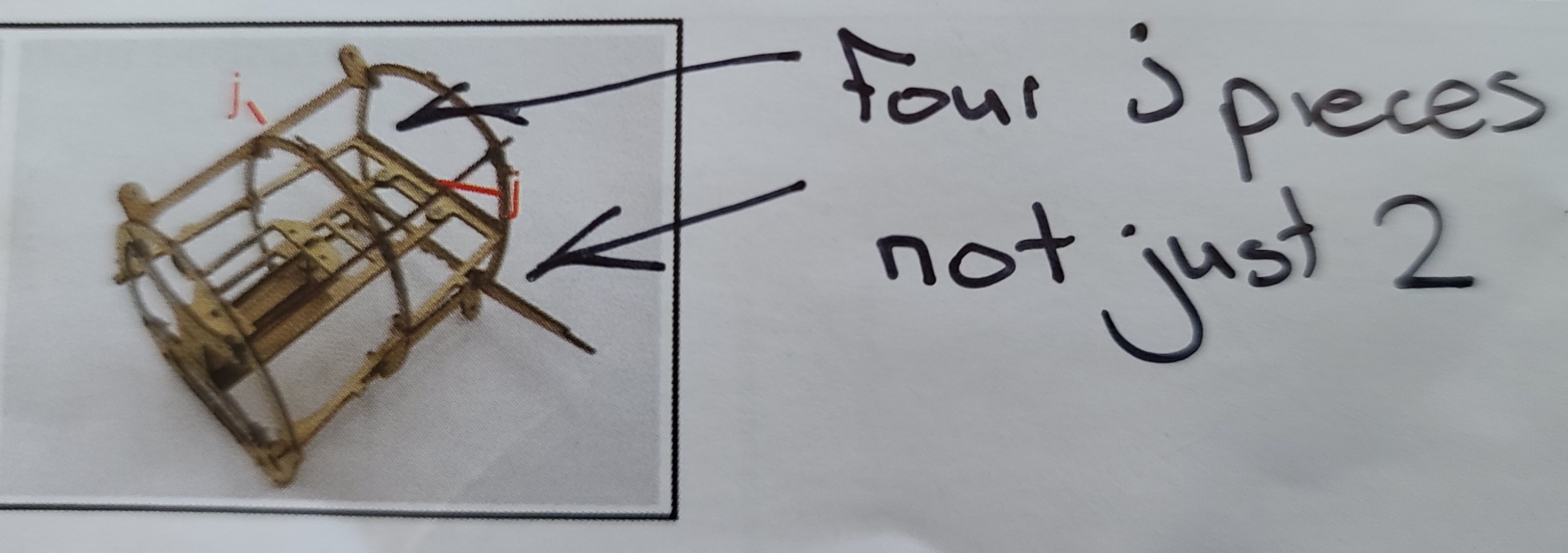
Also – install the “j” pieces before you install “I”, so reverse these pictures.
Don’t put the tail peg in right away.
This is more of a suggestion, but I found it so easy to accidentally break the tail peg when doing other parts of the plane. Perhaps delay installing it until just before you put on the elevator and rudder. Also – soak the tail peg in CA glue/super glue for strength. It is very fragile and needs beefing up.
Watch out for the Q ribs
When building the wings there are whole lot of “R” ribs, but only 2 “Q” ribs which go on the very inside of the lower wing. Pay attention to this and don’t accidentally put the Q ribs somewhere else.
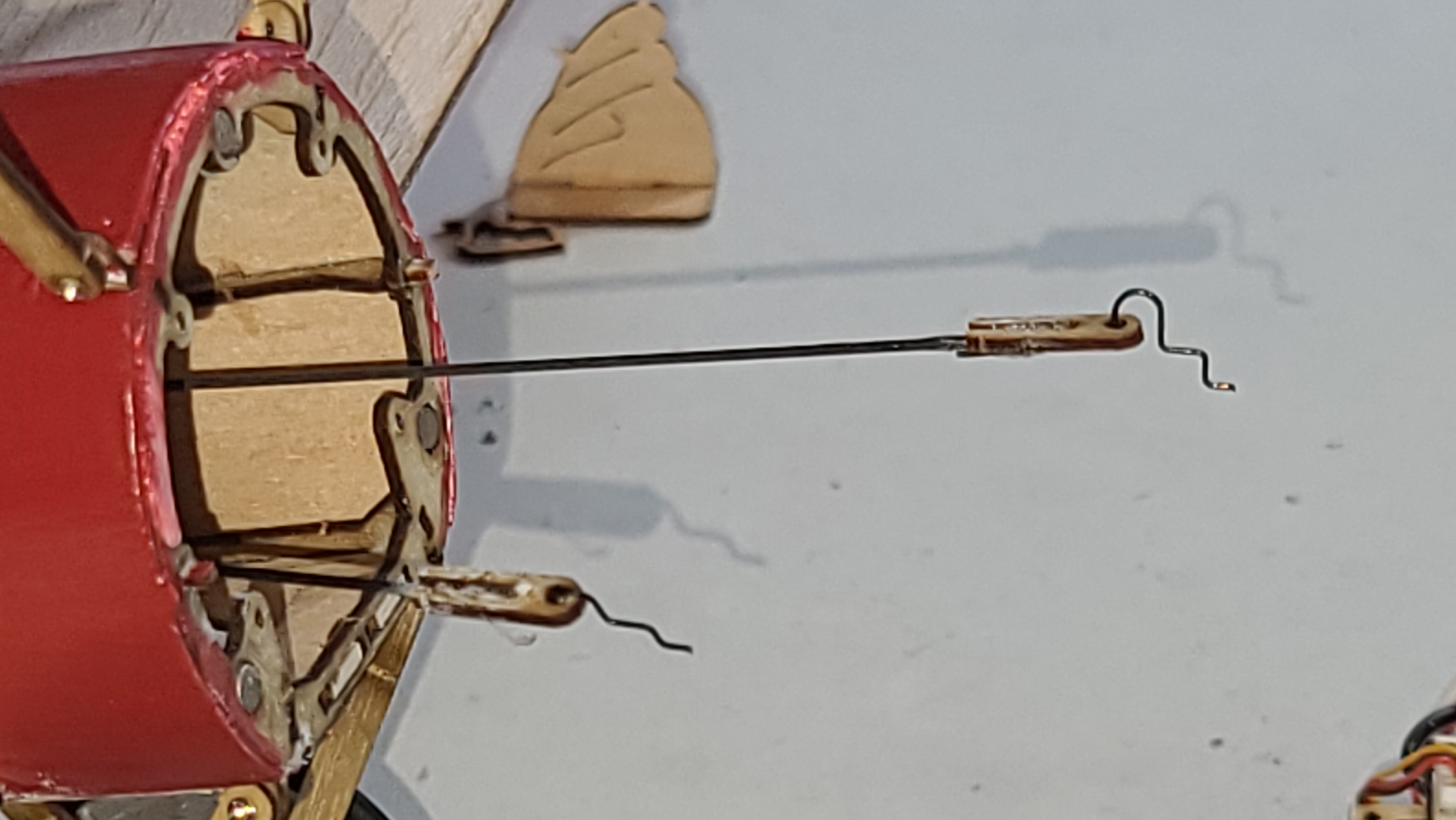
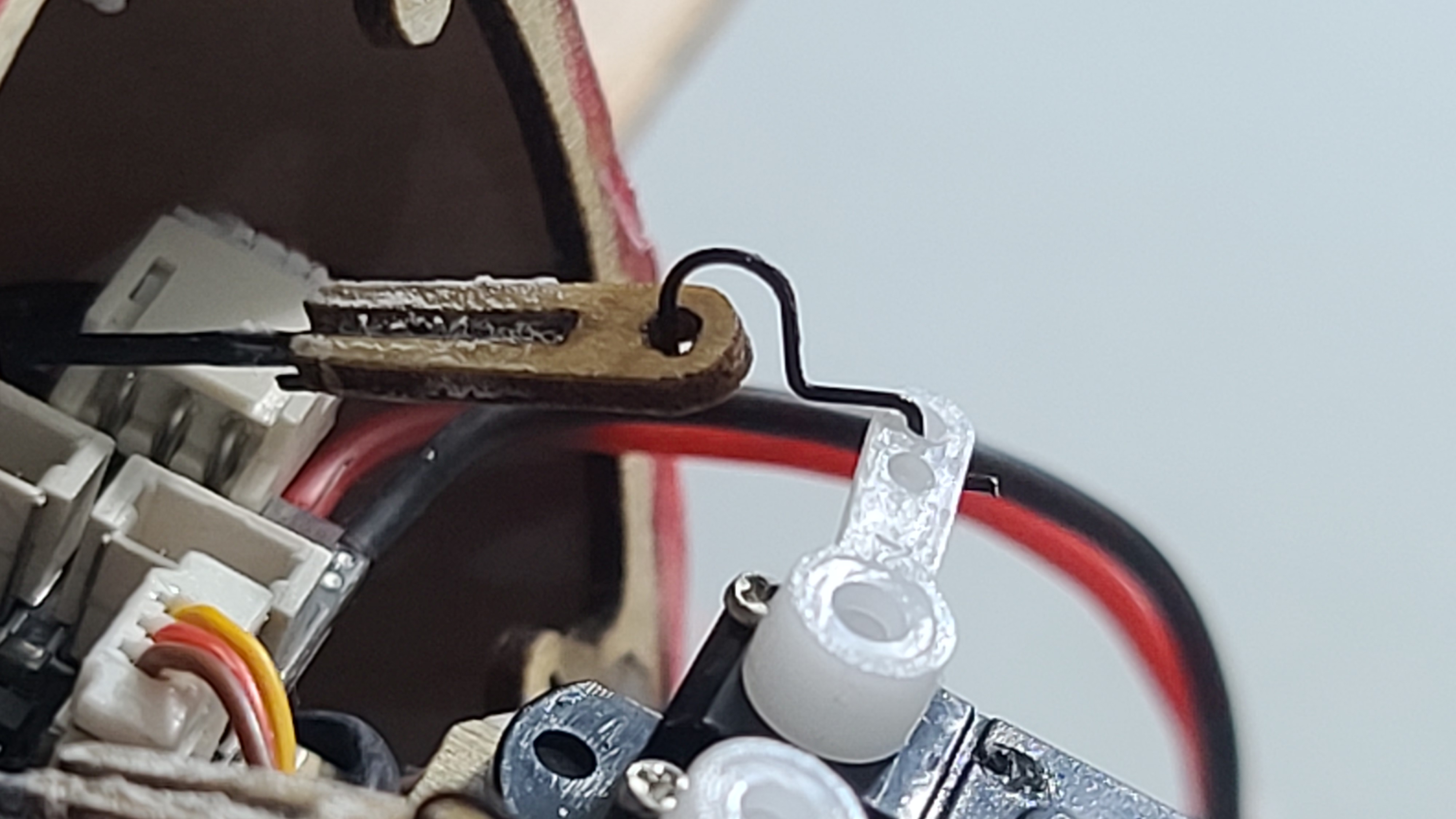
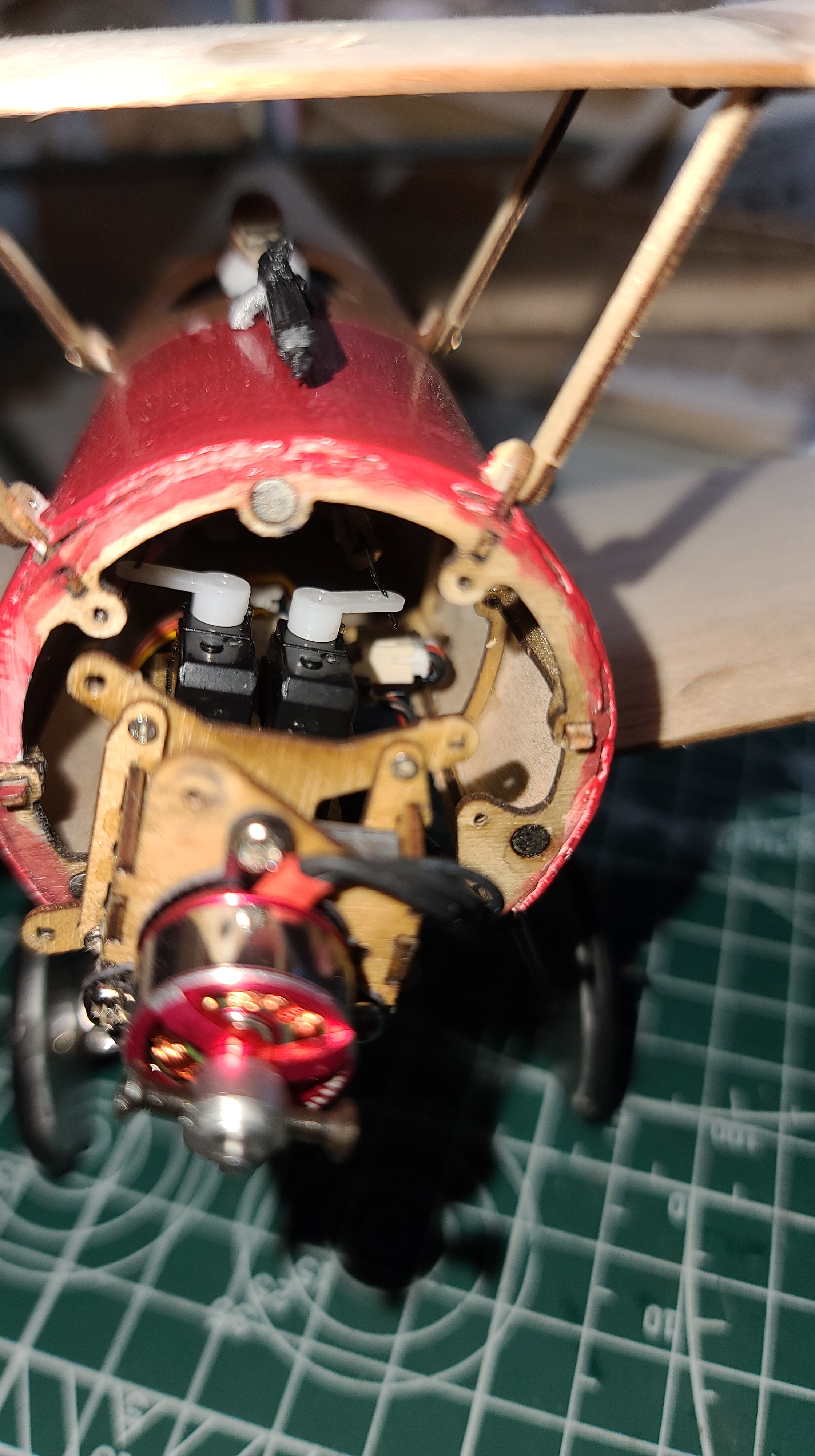
How to connect the pushrods to the servos
The Instructions at Step 6, picture 5 shows how to connect the “6” wooden pieces to the end of the pushrods and then attaching them to the servo arms. But the picture is all you get and it’s really not clear how to connect the wire pieces provided to the servo arms. Zooming in the picture on the instructions doesn’t make it clear, because the picture is so grainy.
So I made my best guess and here are pictures showing how I did it. Take note of the two pictures showing the pushrod connection to the servos. One works and one doesn’t. I tried the first and it seemed fine, but the plane flew around in a circle because the pushrods were catching on the inside of the fuselage. Do it the second way, this brings the rods down lower and away from the fuselage.
It works! (Maybe there is a better way, but this way works).

Glue the wheels (carefully!)
You don’t want the wheels to stick, they work and I got some really nice takeoffs from the kit wheels. I guess it should have been obvious, but the wheels need to be glued to the nylon bushes and the o-ring “tires” need to be glued to the wooden rims. If you don’t you run the risk of them popping off on the field. I used “super glue” (CA glue) because it is plastic to wood and rubber to wood. Be very careful not to get any glue inside the bush so that the wheel can spin nicely on the axle.
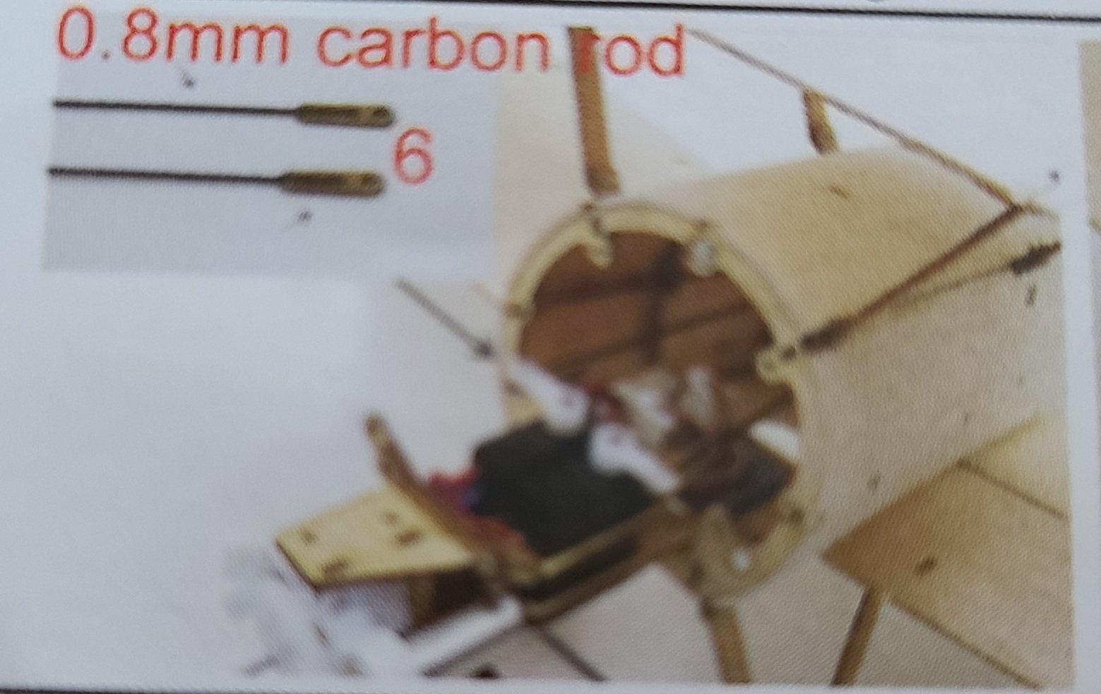
Reinforce the undercarriage
I flew my plane on a wonderful field with some very thick grass which cushioned my many crashes while I was tuning it. What did happen a number of times when crashing or even having a good landing, was the undercarriage would break off when it hit the grass. So I reinforced it with 4 pieces of carbon fiber rod. This also helped with the centre of gravity because the undercarriage is mostly forward of the CoG.

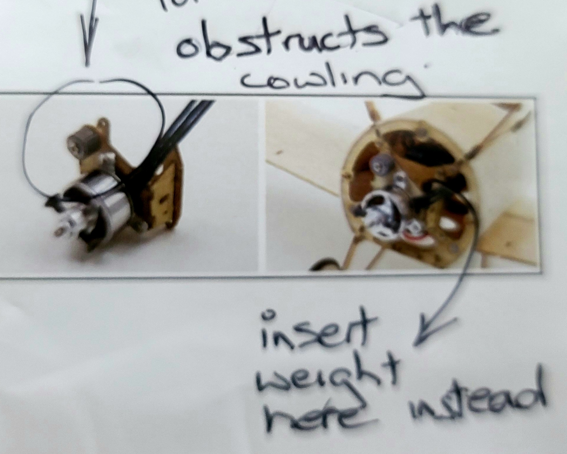
If using a brushless motor don’t install the lead weights as per the Instructions.
If you put the lead weight at the top of the special mounting base shown in “8. Assemble the Brushless Motor”, you will not be able to put the cowling on. Following the build instructions for “brushless motor”, the weight wrapped around the screw gets in the way, preventing the cowling from being clicked onto it’s magnet.
Instead, I suggest you install any weight required in the bays behind the motor, there is one at the top and one at the bottom.
You will need a lot of weight. The included weight was not enough to get the centre of gravity right for me. I had to add more, for a total of 12g, to get it the centre of gravity to where it should be according to the instructions.
I actually needed a lot of weight to bring the centre of gravity forward in order for the plane to fly. I didn’t keep track of it all, but here are some pictures. The weight that came with the kit + two pieces of solder + some ‘white tack’ plastic putty packed into the cowling. I’m sure it’s more than 10g all up.
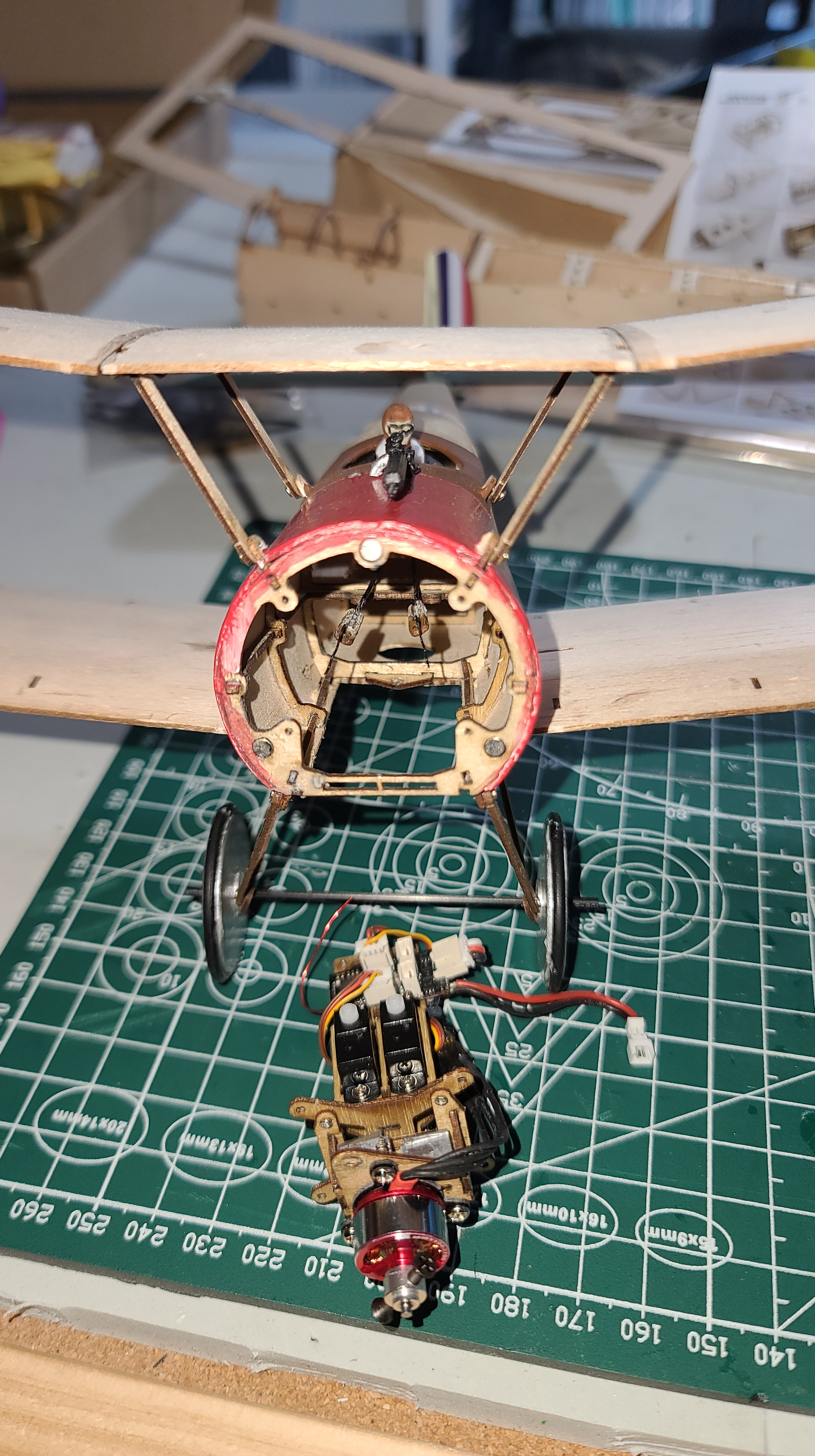
Installing the recommended brushless MM1104 motor is tricky
There are combo packs online (e.g. Amazon where I bought mine) that include the recommended MM1104 motor from AEORC. When you try to screw the motor onto the provided special mounting base, it will not fit cleanly. I had to drill new holes because the provided ones didn’t line up with the holes on the triangular engine mount. Even then, one of the screws barely has any purchase on the mounting plate. It does work though, although it doesn’t look tidy, and the plane will fly with this motor mounted to the mounting base. Here are a couple of pictures that show how it looks:
Specifications
This is what I used to build the plane.
Motor: Brushless Motor: MM1104 3700KV (included with the kit from Amazon)
Receiver: AEORC Rx144-E DSMX compatible mini micro receiver with built in 5A/1S ESC. Note the “E” – this is the one with the built in brushless ESC, without the E, you will need an external ESC.
Receiver manual at http://bit.ly/3estN0J
ESC: Not required because the Rx144-E has a built in brushless ESC
Servos. 1.7 g micro servos x2 (included with the kit from Amazon)
Battery: 150 mAh 1S 30C Lipo 200mAh 30C 1S recommended. I got this one from BangGood
Total weight for these electronics is 15g.
Jumper T-Lite OpenTX transmitter settings
I found transmitter setup was critical to getting the Sopwith Pup to fly well. The elevator is very twitchy, so I reduced the rate (weight) on the elevator to 66% and with a 35% exponential (expo). The rudder on the other hand needs all the throw it can get, so I have the weight at 100%, but the expo at 30% which worked quite well.
Final Comments
The model as built following these instructions, with painting, looks great! I am very happy with the look, everything is working and with some tuning after the maiden flight and some additional test flights.
But it’s very heavy. 65.5g total weight. The specifications for the plane say flying weight is 42-50 grams, so it is 15.5 grams overweight.
If I weight the model with the painting that I did, it comes out to 70g. I built the same model again without painting – 65g, but I don’t think I could get it any lighter.
I don’t want to break my lovely plane, so I have ordered a new kit, and I’ve built it again, bare bones, following my instructions above. So the extra weight isn’t a problem, it really does “fly like a bird”.
[And I’ve updated this blog based on the second build, so the hints and suggestions you see are what you need to build your own].

Excellent advice. I built one of these several years ago, when it came with a dual motor brushed system. Mine came out at about 65g as well, with a LOT of weight required in the nose. Despite that though, it does fly, and looks good.